Coriolis flow measurement: simultaneously measures mass flow, density, temperature and viscosity
The FTM-1600 flow meter is based on the Coriolis measurement principle and is widely used in different industry sectors such as life sciences, chemicals, petrochemicals, oil and gas, food, and not least in custody transfer applications. Coriolis flow meters can measure almost all fluids: detergents, solvents, fuels, crude oils, vegetable oils, animal fats, latex, silicone oils, alcohols, fruit solutions, toothpaste, vinegar, ketchup, mayonnaise, gases or liquefied gases.
Simultaneous measurement of mass flow, density and temperature opens up completely new prospects for process control, quality assurance and plant safety.
Special density values such as reference density, Brix, Baum, API, etc.
Coriolis flow measurement principle
Each Coriolis flow meter has one or more measuring tubes, and an exciter causes the measuring tubes to artificially oscillate. Once the fluid starts flowing in the measuring tube, an additional twist is imposed on this oscillation due to the inertia of the fluid. The two sensors detect this change in the tube's oscillations in time and space, called the "phase difference." This difference is a direct measure of mass flow. Furthermore, the fluid density can be determined from the oscillation frequency of the measuring tube. The temperature of the measuring tube was also recorded to compensate for thermal effects. The resulting process temperature can be used as an additional output signal.
Benefits
Universal measurement principles for liquids and gases
Multivariable measurement – simultaneously measures mass flow, density, temperature and viscosity
High measurement accuracy: typically ±0.1% or optionally ±0.05% or (PremiumCal)
The measuring principle is independent of physical fluid properties and flow curves
No import/export required to run
How accurate is a Coriolis flow meter?
mass flow measurementIt is the basis for most formula formulations, material balance determinations, and billing and custody transfer operations in most industries that require flow measurement. Since these are the most critical flow measurements in a process plant, the reliability and accuracy of mass flow detection is very important.
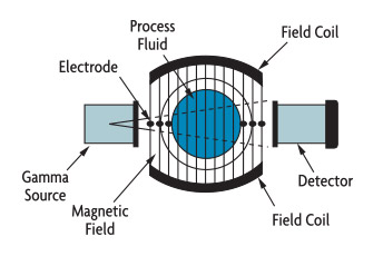
In the past, mass flow was often calculated based on the output of volumetric flow meters and density meters. Density can be measured directly (Figure 5-1A) or calculated using the output of process temperature and pressure transmitters. These measurements are not very accurate because the relationship between process pressure or temperature and density is not always precise - each sensor adds its own independent error to the overall measurement error, and the response of this calculation is often not fast enough to detect step changes in flow.
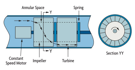
One of the early designs of self-contained mass flow meters operated using angular momentum (Figure 5-1B). It has a motor-driven impeller that transfers angular momentum (rotational motion) by accelerating the fluid to a constant angular velocity. The higher the density, the greater the angular momentum required to obtain that angular velocity. Downstream of the driven impeller, a spring-loaded stationary turbine is exposed to this angular momentum. The torque produced (spring torsion) represents the mass flow rate.
These instruments have moving parts and complex mechanical designs. Methods were first developed for measuring aircraft fuel, and some are still in use. However, due to their complexity and high maintenance costs, they were gradually replaced by sturdier designs that required less maintenance.
Mass flow can also be measured by batch weighing or by combining an accurate level sensor with a density meter. Another method is to install two d/p transmitters in the lower part of the large atmosphere tank at different heights. In this case, the output of the top d/p unit will vary with the level in the tank, while the output of the lower d/p unit will measure the hydrostatic head over a fixed elevation distance. This pressure difference creates the density of the material in the tank. Such systems have been used to measure the total mass flow of slurries.
Answer: Magnetic current and radiation density (Figure 5-1A)
B: Angular momentum (Figure 5-1B)
Interference
The Coriolis force has little effect on the vibrating tube. Full-scale flow may result in deflection of only 0.001 inch. To achieve a 100:1 flow range, the sensor must be able to detect deflection with 0.000001-inch accuracy in an industrial environment where process pressure, temperature, and fluid density all vary and pipe vibration interferes with measurements.
The elasticity of metal tubes changes with temperature. As they warm, they become more resilient. In order to eliminate corresponding measurement errors, the tube temperature is continuously measured by RTD elements and used to continuously compensate for changes in tube elasticity.
Coriolis mass flow meters are usually calibrated on water because the constant is valid for all other liquids. Density calibration is usually accomplished by filling a test tube with two or more (stagnant) calibration solutions of known density.
Accuracy and range
Coriolis meters provide 0.1-2% rate error over a mass flow range up to 100:1. Typically, curved tube designs offer a wider range (100:1 to 200:1), while straight tube meters are limited to 30:1 to 50:1 and are less accurate. The total instrument error is the sum of the fundamental error and the zero-displacement error, which is attributed to the irregular output signal produced under zero-flow conditions. The zero displacement error becomes the dominant part of the total error at the lower end of the flow range, where the error is between 1% and 2% of the ratio. Some manufacturers express overall accuracy as a percentage of rate in the upper part of the flow range and a percentage of span in the lower part, while others express it as a percentage of rate versus zero displacement error. There are quite a few "features"
When used for density measurements, the typical error range for Coriolis measurements is 0.002-0.0005 g/cc.
Errors are caused by air pockets or air pockets in the process fluid. In the case of uniformly dispersed small bubbles, more energy is required to vibrate the tube, whereas if the gas phase separates from the liquid, a damping effect on the tube vibrations (and therefore errors) occurs. Small voids can also cause noise due to sloshing of process liquid in the tube. Larger voids increase the energy required to vibrate the tube to excessive levels and can lead to complete failure. Because flow meters are subject to axial, bending, and torsional forces during meter operation, if these forces are altered by process or ambient temperature and pressure fluctuations, performance may be affected and the meter may need to be rezeroed.
Changes in process fluid density can affect the frequency transfer function of a mechanical system, making it necessary to re-zero old designs to prevent their performance from degrading. Because of their tube configuration, newer designs are not affected by density changes over a wide range of specific gravity changes.
Dimensions and pressure drop
Due to the wide range of Coriolis flow meters (from 30:1 to up to 200:1), the same flow rate can be measured through two or three different sized flow tubes. By using minimal instrumentation, initial cost is reduced and coating build-up is reduced, but corrosion/corrosion rates and head losses are increased, thereby increasing pumping and operating costs.
When a pipe is oversized and the process fluid is clean and has low viscosity, it can be downsized (using a smaller gauge than the pipe). Downsizing is not recommended in corrosive, sticky or abrasive slurry service. A list of acceptable flow tube sizes and corresponding pressure drops, inaccuracies, and flow rates can be obtained from the software provided by the manufacturer.
Different Coriolis meters will produce different pressure drops, but in general they require more pressure than traditional positive displacement meters (usually at pressures below 10 psid). (The annual electricity bill to pump 1 GPM between 10 psid pressure differential is about $5). Higher head losses are caused by reduced pipe diameter and the reverse flow path. In addition to pumping costs, head loss is also a concern if the meter is installed in a low-pressure system, or if cavitation or flash evaporation is likely to occur, or if the fluid viscosity is very high.
The viscosity of a non-Newtonian fluid is a function of its flow rate. For example, Dilettante fluids increase their apparent viscosity (resistance to flow) as velocity increases. The apparent viscosity can be significantly higher than the stagnation viscosity. To provide suppliers with data on flow viscosity in a specific pipe, the head loss per foot of pipe (used in pump sizing calculations) can be used as an approximation.
DOWESTON provides you with high-precision temperature sensors, including thermal resistors and thermocouples, and provides temperature calibration services.
Our experts are ready to helpWherever you are, DOWESTON's experienced engineering team is ready to support your product selection and applications - contact us today!
Tell us about your measurement task and we will help with product selection and technical questions.info@doweston.com
We value your privacy!
We and our partners use cookies and similar technologies to process personal data (such as IP address or browser information) in order to personalize the content and advertising shown to you. This helps us display more relevant content and improve your browsing experience. We also use it to measure results and tune website content. Because we value your privacy, we are asking for your permission to use these technologies. You can change or withdraw your consent at any time by clicking the settings button in the lower-left corner of the page.





 Home