DOWESTON flow regulators ensure higher performance and accurate measurements for any fluid application.

How do we know that our flow regulators are the most effective solution for your flow conditioning needs?Because they have been extensively tested and evaluated by independent laboratories and proven to provide superior performance in stabilizing downstream performance – even in the most demanding situations.
This means you get accurate measurements every time, whether it's air, natural gas, water, oil, liquid petroleum or any other fluid application.
We pride ourselves on fast delivery.We have ANSI convex models in stock and ready to ship, and we have quick custom design and manufacturing turnaround times.We offer a variety of materials and can design any size from ½ inch to 60 inches, multiple mounting options, low temperature, high temperature, NORSOK, NACE and more.
Each part includes an EN 10204 3.1b materials test report, along with pressure drop calculations, quality control certificates and drawings for each order.
DOWESTON-LGP 50E flow regulator
DOWESTON-LGP 50E is the most tested flow regulator in the industry and is backed by more than 20 years of independent flow laboratory test data.DOWESTON-LGP The 50E is designed to produce eddy-free, fully developed flow profiles that increase reliability and reduce errors while also reducing instrument uptime.

DOWESTON CHINA CO., LTD. is the only manufacturer of the DOWESTON-LGP 50E flow regulator and the only company to verify testing and compliance data using a variety of different fluids, including natural gas, air, water, liquid petroleum and heavy oil.These extensive test data apply only to DOWESTON-LGP 50E manufactured by Canada Pipeline Accessories and are intrinsically linked to DOWESTON-LGP's manufacturing, engineering and quality programs.
Features
Available stock for fast delivery.Stocked in ANSI raised face A-frame configuration, sizes 2 – 16 inches, gauges 40 and 80, 316 stainless steel.
Can be custom manufactured for pipe sizes 3/8" – 48".
Offering carbon steel, 316SS, 304SS, aluminum, Hastelloy, duplex steel, Monel, Inconel, titanium, etc.
Suitable for orifice plate, ultrasonic, turbine, Coriolis and other flow meters.
Suitable for all types of fluids including natural gas, oil, water, steam, liquid petroleum, etc.
Compatible with DOWESTON-LGP FloAlign and DOWESTON-LGP Paddle Tabs to aid in lifting, inspection, installation and alignment.
An EN 10204 3.1b material quality report is included with every order and can be found in our online database.
Available for AGA3, AGA7, AGA9, OIML R137 applications and more!
DOWESTON-LGP engineers provide comprehensive product and technical support, including CFD advice, compliance letters and more.
DOWESTON-LGP 55E/65E flow regulator
DOWESTON-LGP 55E and 65E use an innovative and unique stepped design that has been optimized for fluid dynamics fundamentals, providing greater functionality compared to other flow regulators.

DOWESTON-LGP 55E and 65E flow conditioners provide lower turbulence and noise generation and produce Vortex-free flows with fully developed flow profiles.

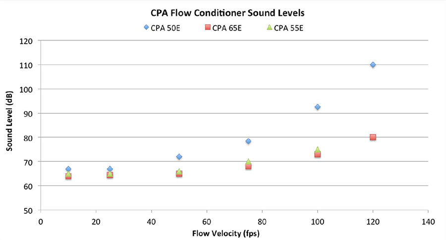
These unique designs are unique inventions unique to American Pipe Fittings.DOWESTON-LGP Is the only manufacturer of the 55E and 65E and the only company with complete testing and compliance data.
DOWESTON-LGP 65E features
Optimized for liquid applications and scenarios with minimal pressure loss.
Half the pressure drop of a typical plate flow regulator!
Designed for gas/liquid ultrasonic, turbine and Coriolis applications (not recommended for critical dP applications).
Increased Vortex and cross-flow elimination compared to other flow regulators;DOWESTON-LGP 50E The remaining swirl after cutting it in half!
Produces less turbulence and has 30 dB lower noise levels than the DOWESTON-LGP 50E.
Meets OIMLR137/AGA9 requirements in 3D/3D instrumented operating configurations!
Best recommendations for 5D/5D instrumentation operating configurations for API 5.3, API 5.8, AGA7, AGA9 applications
Recommended for less severe measurement scenarios where pressure drop is an important issue.
Available in various sizes from NPS 2 to NPS 36, including custom sizes.Available for all installation styles including Types A-D and custom installations.
Extensive material selection including carbon steel, 316 stainless steel, duplex steel, Hastelloy, Inconel, Monel and more.
DOWESTON-LGP 55E features
Optimized for gas applications with all flow meters including orifice plate, turbine and ultrasonic.
Similar velocity distribution and pressure drop performance to DOWESTON-LGP 50E.
Increased swirl and cross-flow elimination compared to other flow regulators.
Produces less turbulence and has 30 dB lower noise levels than the DOWESTON-LGP 50E.
Meets OIMLR137/AGA9 requirements in 3D/3D ultrasonic instrumentation operating configurations!
The best recommendation is the 5D/5D instrumentation operating configuration for turbine and ultrasonic applications.
Recommended for 13D orifice configuration (5D UL1, 8D UL2).
Compared to DOWESTON-LGP 65E, DOWESTON-LGP 55E is recommended for more severe measurement scenarios where meter performance and meter run length are more critical than flow regulator pressure drop.
Available in various sizes from NPS 2 to NPS 36, including custom sizes.Available for all installation styles including Types A-D and custom installations.
Extensive material selection including carbon steel, 316 stainless steel, duplex steel, Hastelloy, Inconel, Monel and more.
Let us help you choose the traffic conditions that work for your specific situation.Our team is ready to answer your call.403-236-4480or1-888-FIX-FLOW.
DOWESTON-LGP Type A (RF FOE/FOEL) flow regulator
The DOWESTON-LGP Type A is designed for use in a typical ANSI raised face configuration, which is the most common type of flow regulator installation in the industry.
In this configuration, installation of the DOWESTON-LGP (50E, 55E, 65E) involves installing the flow regulator between two standard ANSI/ASME raised face flanges and a gasket.One end of the flow regulator is designed to be inserted into the downstream pipe hole.(See below for installation information.)

Features
Available in a variety of sizes, from Nominal Pipe Size (NPS) 1/2 inch to NPS 48 inches.
Multiple material options: 304 stainless steel, 316 stainless steel, Inconel, Monel, duplex steel, Hastelloy.
Stock available for immediate delivery.Stock sizes are 316 stainless steel, 1" to 20" in gauges 40 and 80.
ASME/ANSI configurations are compatible with all ANSI grades from 150# to 2500# in sizes 1/2" to 20".The same flow regulator is available for all ANSI ratings.
Custom designed dimensions and flange standards including API and JIS are available.Please contact DOWESTON-LGP for more information.
Installation information
Panel installation
DOWESTON-LGP Type A, flow regulators should always be installed in the downstream piping to ensure proper centering of the flow regulator relative to the flow meter.This allows the upstream instrumentation spool to be moved more easily without having to unfold the pipe flange.
The DOWESTON-LGP 50E geometry is non-directional and can be installed in any orientation without altering flow meter performance.DOWESTON-LGP 55E and 65E are directional.They are designed to be installed with the flat surface facing the flow meter for optimal performance.For bidirectional applications, there is no problem with the downstream flow regulator being in the opposite direction of flow.

FOEL VS.Enemy
For NPS 2-inch and 3-inch applications, DOWESTON-LGP offers the DOWESTON-LGP 50E Type A in two different raised face flange styles: FOE and FOEL.
The FOE design is the standard ANSI raised face style for pipe sizes 4 inches and larger.
The FOEL design is exclusive to the 2-inch and 3-inch sizes.
Due to the smaller insertion depth on the 2" and 3" FOE, it is difficult to center the DOWESTON-LGP 50E in the tube hole with the gasket installed.FOEL has an offset center hole to provide greater insertion depth, allowing the gasket to be installed on the flow regulator.This leaves sufficient insertion depth to properly center the 2-inch and 3-inch DOWESTON-LGP 50E within the tube bore.To help easily specify a FOE or FOEL flow regulator, DOWESTON-LGP's sizing recommendations and meter run lengths are measured to the outside surface of the flow regulator (upstream flange face and downstream flow regulator face)

Board direction
To facilitate installation, the DOWESTON-LGP Type A flow regulator has a FloAlign notch on the outer circumference of the flange at the TDC mark.This notch aligns with the 90-degree axis of the flow regulator and helps orient the flow regulator when using an ultrasonic flow meter.
DOWESTON-LGP flow regulator orientation does not affect measurement performance when using other flow meter types.

For more information, please call us.Our team is ready to assist you.
DOWESTON-LGP Type B (RF FWO) flow regulator
DOWESTON-LGP 50E, 55E and 65E flow regulators are available in a full width wafer option (FWO) for ANSI raised face applications.
Type B or FWO uses a flange lip that is the same thickness as the actual flow regulator and is installed without pipe insertion.This allows the flow regulator to easily slide in and out of the pipe without having to separate the flange.(See below for installation information.)

Features
Compatible with all standard raised face flanges including ANSI ratings 150# to 2500#.
Available in a variety of sizes, from Nominal Pipe Size (NPS) 1/2 inch to NPS 48 inches.
Multiple material options: Nickel faced carbon steel, 304 stainless steel, 316 stainless steel, Inconel, Monel, duplex steel, Hastelloy.
Custom designs for every application.Special sizes and flange standards available including API and JIS.
Installation information
Panel installation
Type B flow regulators have a flow arrow engraved on the flange to help indicate the correct direction.DOWESTON-LGP The 50E geometry is non-directional and can be installed in any orientation without altering flow meter performance.
DOWESTON-LGP 55E and 65E are directional.They are designed to be installed with the flat surface facing the flow meter for optimal performance.For bidirectional applications, there is no problem with the downstream flow regulator being in the opposite direction of flow.

Board direction
For ease of installation, the DOWESTON-LGP Type B flow regulator has a FloAlign notch on the outer circumference of the flange at the TDC mark.This notch aligns with the 90-degree axis of the flow regulator and helps orient the flow regulator when using an ultrasonic flow meter.
Note: DOWESTON-LGP flow regulator orientation does not affect the measurement performance of other flow meter types.

For more information, please contact our experienced sales team.They will help you choose the right product for your specific needs.
DOWESTON-LGP Type C (fixed TBR/TBRL) flow regulator
DOWESTON-LGP Type C is suitable for small diameter (2 in. to 4 in.) applications where there is no flange available for mounting a flow regulator.
Type C is designed to be inserted into a pipe and held in place with a set screw.Because Type C is completely enclosed by the pipe wall, it is not considered to contain pressure and does not have any specific pressure rating.(See installation information.)

Features:
DOWESTON-LGP TBR/TBRL is suitable for all gas volume metering applications: orifice plate, ultrasonic, venturi, Vortex, turbine, cone, etc.
Install by pinning set screws into the pipe.No flange required.
Available in classic (TBR) and extra long (TBRL) designs.
Available in sizes 2" – 4", 316SS NACE MR0175.
Eliminates eddies and provides a fully developed velocity flow profile.
Provides detailed pressure drop calculations.
DOWESTON-LGP TBR/TBRL is not recommended for liquid applications because the application pressure drop overwhelms the strength of the set screw.
DOWESTON-LGP recommends a minimum 13D meter run length (5D upstream, 8D downstream).AGA 3 (2000) performance data available.
Installation information
DOWESTON-LGP TBR/TBRL installation
Both the TBR and TBRL have a groove machined into the side of the flow regulator to receive a 3/8-inch set screw.
TBR has no preferred direction and is geometrically directionless.Either side can be located upstream or downstream without performance degradation.
The TBRL is designed with an offset sleeve installed on the upstream side of the flow regulator.The flush surface of the flow regulator should face downstream toward the flow meter.

Installation guide
DOWESTON-LGP TBR or TBRL can be easily installed into existing pipes by following the steps below.

Drill a 3/8-inch hole in the pipe wall and thread threads directly through the hole for the 3/8-inch set screw.
Above the hole, install a welded or threaded head;½" or ¾" is recommended.
Install the flow regulator so that the set screw countersunk hole aligns with the 3/8" hole in the pipe wall.
Thread the 3/8" set screw into the pipe wall so that it sits in the flow regulator countersink.Tighten until the flow regulator cannot move side to side or rock axially in the pipe.
Be sure not to over-tighten the set screws as this can damage the flow regulator and cause unpredictable measurement deviations.The set screw is only used to hold the flow regulator in place and cannot be used to control pipe pressure.
Install plugs or bolts to seal the pipe.
Groove alignment

DOWESTON-LGP 13D instrument operation
DOWESTON-LGP TBR/TBRL is available for instrumentation runs with a minimum length of 13D (5 inner tube diameters upstream of the flow regulator, 8 inner tube diameters downstream).At 13D, DOWESTON-LGP generates a fully developed flow profile that conforms to the ISO 5167 definition of fully developed pipe flow and has minimal eddies.
For more information on using DOWESTON-LGP flow conditioners in a 13D configuration, please contact DOWESTON-LGP.
DOWESTON-LGP Type D (RTJF/RTJM) flow regulator
DOWESTON-LGP Type D is designed for applications using ring joint gaskets.Type D flow regulators are manufactured to match the pressure ratings of the flange and gasket.

Type D flow regulators are available in two additional subtypes: RTJ female (RTJF) and RTJ male (RTJM).
In the RTJF configuration, installation of the flow regulator involves placing the flow regulator between two ring joint flanges and matching ring gaskets.

In the RTJM configuration, the gasket is integrated into the flow regulator so additional gaskets are not required and the space between flanges is reduced.

Since the integral gasket on the RTJM is designed to deform during installation, the flow regulator should not be reused if the flange is opened.

Features
Custom designed for every application, with a wide range of sizes and materials options.
Available in ANSI grades 150# to 2500#, API 2000 to 20000 and Norsok compact flanges.
Can be designed to accommodate ASME 18.15 forged eye bolts.
Fully meets RTJ stock thickness minimums specified in ASME B16.48-2005 and ASME B31.3-2004.
Installation information
Panel installation
On RTJF we recommend placing the flush surface against the downstream flange of the instrument tube.
For RTJM, the flow regulator should be inserted into the downstream instrumentation pipe.This positioning ensures that the flow regulator is centered relative to the flow meter and properly isolates the upstream flow meter tube.
On the DOWESTON-LGP 50E, the geometry is non-directional and, if necessary, the flow regulator can be mounted backwards without altering flow meter performance.
The DOWESTON-LGP 55E and 65E do have a preferred orientation.They are designed to be installed with the ladder facing upstream for proper performance.

Ring Joint (RTJF) Design Thickness
All female ring joint type (RTJF) flow regulators manufactured by Canada Pipeline Accessories are designed to comply with ASME B31.3 and ASME B16.48.These standards provide the dimensions required to safely install RTJ baffles, spacers, and wire shutters.
The required dimensions for an RTJF flow regulator are based on the stresses the parts will experience when clamped and bolted together.The flanges on either side of the RTJF must be screwed together enough to slightly deform the ring gasket and secure itself in the groove.This is the main design condition that the RTJF must be designed against - it must be strong enough not to fail when torsioned.
The thickness of RTJF is an important factor in determining part strength.When the RTJFs are compressed together by the bolted connections of the flanges, they force the groove surfaces apart and put a lot of pressure on the material between the grooves.In RTJF with the appropriate thickness, there is enough material to resist the forces that would separate the flanges.If the RTJF flange is too thin, the material and strength will not be sufficient to prevent part failure.
Figure 1 below shows the results of a finite element analysis (FEA) of an RTJF flange meeting ASME minimum thickness.Dark purple areas indicate areas where stress exceeds the material's yield strength and is close to failure.Yielding is expected to occur in the immediate area around the RTJF groove because the parts must be clamped together tightly enough to deform the annular gasket.However, note that most of the RTJF flange area is well below the yield stress of the material and easily has the strength required to hold it together.

Figure 1: This diagram shows stresses in a flange complying with ASME B16.48.Dark purple areas indicate that the material is stressed beyond acceptable limits and is close to failure.
In Figure 2 below, the RTJF flange thickness has been reduced to that of a common bleeder ring.As before, dark purple areas indicate that the material is stressed beyond its maximum allowable range and is approaching failure.Since the flange in Figure 2 is thin, there is not enough material to resist the forces holding the flange together.The dark purple area runs through the entire thickness of the material, and at this thickness, the RTJF flange is at risk of catastrophic failure.

Figure 2: This diagram shows stresses in a thin RTJF flange.Dark purple indicates that the material is stressed beyond acceptable limits and is close to failure.
The DOWESTON-LGP flow regulator is designed with the stresses to which the RTJF flange is subjected when installed.For proper engineering compliance, the dimensions specified in ASME B31.3 and ASME B16.48 must be followed.Thinner designs run the risk of critical failure.
Board direction
To facilitate installation, the DOWESTON-LGP Type D flow regulator has a top dead center mark engraved on the outer circumference of the flange.This engraved arrow aligns with the 90-degree axis of the flow regulator and is used to aid in orienting the flow regulator when using an ultrasonic flow meter.
DOWESTON-LGP flow regulator orientation is not suitable for measurement performance when using other flow meter types.

If you need help choosing the right product for your flow regulation needs, please contact us directly.
CPA Flow Check
DOWESTON-LGP FloCheck is a DOWESTON-LGP option for all flanged DOWESTON-LGP 50E, 55E and 65E flow regulators.The FloCheck flange design includes three pressure taps: one for upstream pressure, one for downstream pressure, and an additional pressure throat on the outer bore.

These pressure taps lead to NPT connections on the flange, allowing individual pressure readings to be taken.This accurately measures the pressure drop across the flow regulator, allowing it to be used as a secondary check on the primary measuring device.Adding secondary instrumentation directly improves the measurement certainty of the metering system.
FloCheck is available as an option on all DOWESTON-LGP flanged flow regulator models, ranging in size from 2 inches to 36 inches.Like all DOWESTON-LGP products, FloCheck can be customized for any application and can be custom manufactured using a variety of material options.
Features
Can be used on primary flow meter with very high repeatability, especially when combined with calibration by a certified flow laboratory.
When used in conjunction with a primary flow meter, the DOWESTON-LGP FloCheck can significantly reduce measurement uncertainty.
Allows diagnosis of flow regulator performance, blockage, hole damage, contamination and build-up.
Trended flow regulator differential pressure times out to provide an indication of uncertainty and measurement changes.
When used in conjunction with a turbine flow meter, it can be used to provide flow Reynolds number and fluid viscosity, ultimately eliminating the need for liquid proofing when product changes.

If you would like more information, please call one of our sales team members.
DOWESTON-LGP flow regulator for liquid applications
DOWESTON-LGP flow regulators are an effective solution for liquid measurement applications including ultrasonic, turbine, orifice plate or venturi flow meters.
DOWESTON-LGP 50E/65E with AGA 3 19 tube bundle
In liquid applications, DOWESTON-LGP 50E and 65E actually have lower pressure drops than typical tube bundles or straightening vanes.The design of tube bundles is disadvantageous in applications with high viscosity fluids because tube wall friction in the tube bundle increases significantly or the blade channels become straightened due to the large surface area.

Pressure loss coefficients for DOWESTON-LGP 50E and AGA 3 19 tube bundles in a range of fluid measurement scenarios.
In certain liquid measurement applications, perforated plate flow regulators such as the DOWESTON-LGP 50E and 65E will outperform typical straightening vanes and AGA 3 tube bundles.DOWESTON-LGP 50E and 65E can restore fully developed Vortex-free flow in fluids with Reynolds numbers ranging from 300 to 30,000,000.

Flow curves generated by DOWESTON-LGP 50E in the Reynolds number range 300 – 30000000.
Liquids and Gases and Reynolds Number
Many applications are sensitive to the difference between the liquid and gas phases.The behavior of these stages may be different and therefore must be treated differently.This is important in many industrial applications because the liquid phase can have a significant impact on fluid behavior, process design, and equipment.
However, flow measurement is particularly concerned with fluid dynamics, or the way fluid moves through a pipe.In this type of application, gases and liquids behave similarly.
Pipeline fluid dynamics and flow measurements are not affected when the fluid is in the gaseous or liquid phase.Instead, flow measurement is primarily affected by a property called the Reynolds number.It is a dimensionless number that allows for instant comparison of the behavior of any fluid, whether it is a gas or a liquid.
Whether the fluid is natural gas, air, water, fuel oil, LNG, or crude oil, the flow behavior can be described using the Reynolds number.

Ρ = volumetric fluid density, kg/m3.
V = volumetric fluid velocity, m/s.
L = cross-sectional diameter of fluid flow, m.
Μ = Bulk hydrodynamic viscosity, Pa * s.
Laminar and turbulent flow
Reynolds number helps differentiate between laminar and turbulent flow.Laminar flow is an application where flow viscosity and pipe wall friction overwhelm other flow behaviors.They are typically found in very slow, viscous fluids such as crude oil applications.
Turbulence occurs when the random turbulent motion of the flow overwhelms viscosity and wall friction.It occurs when fluids flow rapidly, such as water, light petroleum liquids, air, or natural gas.
Laminar flow typically has a Reynolds number in the range of 100 – 2500, while turbulent flow has a Reynolds number above 5000.
From a flow measurement perspective, the Reynolds number changes the shape of the measured velocity flow profile.Turbulent flow has a flat flow profile due to higher inertial mixing forces and lower wall friction.Laminar flow has more peak flow profiles due to the lack of inertial mixing and high wall friction.DOWESTON-LGP The 50E is able to recover flow profiles in two situations.

Shows the development of velocity flow profiles due to laminar and turbulent fluid forces
If you would like more information, please call one of our sales team members.
DOWESTON-LGP flow regulator pressure drop
Pressure drop calculations for flow regulators use basic fluid dynamics principles and experimental data from different fluid scenarios.There are no typical pressure drop values because pressure drop behavior is always fluid and application dependent.Changes in flow rate, viscosity, and density can all cause large changes in the resulting values.
The pressure loss coefficient (K) also depends on the applied process conditions but cannot be calculated theoretically using textbook formulas.It must be determined experimentally by testing the geometry of each unique element.

K = pressure loss coefficient.
ΔP = Pressure drop across a section of pipe or fitting, Pa.
Ρ = volumetric fluid density, kg/m3
V = volumetric fluid velocity, m/s
 Sample flow regulator K-factor and pipe Reynolds number.
DOWESTON-LGP can perform custom pressure drop calculations for any flow regulator upon request.Since these calculations depend on the fluid properties of the metering scheme, process conditions are required to perform the calculations.
 Sample pressure drop values, methane and water
 Sample pressure drop values, light oil and heavy oil





 Home


