With the development of science and technology, PLC is used more and more widely in industrial control. The reliability of the PLC control system directly affects the safe production and economic operation of industrial enterprises. The interference capability of the system is the key to the reliable operation of the entire system. Various types of PLCs used in automation systems, some are installed centrally in control rooms, and some are installed at production sites and on various electrical equipment. Most of them are in harsh electromagnetic environments formed by strong current circuits and strong current equipment. To improve the reliability of PLC control systems, designers must understand various interferences in advance to effectively ensure reliable operation of the system.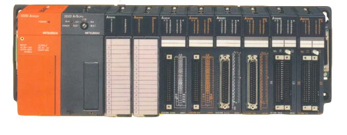
Sources of electromagnetic interference and interference to the system
The interference that affects the PLC control system originates from the same interference sources that generally affect industrial control equipment. Most of them occur in locations where current or voltage changes drastically. These locations where charges move violently are noise sources, that is, interference sources.
Interference types are usually classified according to the causes of interference, noise interference patterns and noise waveform properties. Among them: according to different causes of noise, it is divided into discharge noise, incidental noise, etc.; according to different sound interference modes, it is divided into common mode interference and differential mode interference, which is a relatively common classification method. Common mode interference is the potential difference between the signal and the ground, which is mainly caused by the common mode voltage induced on the signal line by the power grid in series, the ground potential difference and space electromagnetic radiation. The common-mode voltage is sometimes large, especially when electrical power supply rooms with poor isolation performance are used. The common-mode voltage of the transmitter output signal is generally high, and some can be as high as 130V or more. Common-mode voltage can be converted into common-mode voltage through asymmetric circuits, which directly affects measurement and control signals and causes component damage. This common-mode interference can be DC or AC. Common-mode interference refers to the interference voltage used between two levels of signals. It is mainly caused by the coupling induction of space electromagnetic fields between signals and the voltage formed by the conversion of common-mode interference by unbalanced circuits. This voltage is directly superimposed on the signal and directly affects the measurement and control accuracy.
What are the main sources of electromagnetic interference in PLC control systems?
1) Radiation interference from space
Radiated electromagnetic fields in space are mainly generated by transient processes of power networks, electrical equipment, lightning, radio broadcasts, television, radar, high-frequency induction heating equipment, etc., and are often called radiation interference. Its distribution is extremely complex. If the PLC system is placed in the set frequency field, radiated interference will be recovered. Its influence mainly passes through two paths. One is direct interference to the radiation inside the PLC and induced by the circuit. It is the radiation of the PLC communication network and the induction of the communication line that introduces interference. Radiated interference is related to the size of the electromagnetic dry field generated by on-site equipment, especially the frequency. It is generally protected by setting up shielded cables and PLC local shielding and high-voltage relief components.
2) Interference from external leads of the system
Mainly introduced through power and signal lines, it is often called conducted interference. This kind of interference is serious in our country's industrial sites.
3) Interference from power supply
Practice has proved that there are many control system failures caused by interference introduced by the power supply. We have encountered this during engineering debugging, and then replaced the PLC power supply with higher isolation performance. The problem can be solved.
The normal power supply of the PLC system is supplied by the power grid. Due to the wide coverage of the power grid, all spatial electromagnetic interference will induce voltages and circuits on the line, especially changes within the power grid, switching operation surges, starting and stopping of large power equipment, harmonics caused by AC and DC rotating devices, short-circuit transient impacts of the power grid, etc., all pass through the social power line to the power supply side. PLC power supply usually uses an isolated power supply, but its structure and manufacturing process factors make its isolation not ideal. In fact, due to the existence of distributed parameters, especially distributed capacitance, absolutely isolating the room is impossible.
4) Interference caused by chaos in the grounding system
Various signal transmission lines connected to the PLC control system, in addition to transmitting various types of effective signals, will always have the influence of external interference, and can also suppress the interference from the equipment. However, incorrect grounding will introduce serious interference signals, making the PLC control system unable to work normally. The ground wires of the PLC control system include system ground, shielding ground, AC ground and protective ground. The main interference to the PLC system caused by a chaotic grounding system is uneven distribution of grounding points. There are ground potential differences between different grounding points, causing ground loop currents and affecting the normal operation of the system. For example, the cable shielding layer must be grounded at one point. If both ends of the cable shielding layer are grounded, there will be a ground potential difference, and current will flow through the ground potential difference. When an abnormal state occurs and a lightning strike occurs, the ground wire current will be greater.
In addition, the shielding layer, the ground wire and the earth may form a closed loop. Under the action of the changing magnetic field, an induced current will appear in the shielding layer, which interferes with the signal loop through the coupling between the shielding layer and the core wire. If the system ground and other grounding are messed up, the resulting ground circulation may produce unequal point distribution on the ground line, affecting the normal operation of the logic circuits and analog circuits in the PLC. The logic voltage interference tolerance of PLC operation is low. The distribution interference of logic ground potential can easily affect the logic operation and data storage of PLC, causing data confusion, program runaway or crash. The distribution of analog ground potential will lead to a decrease in measurement accuracy and cause serious distortion and malfunction of signal measurement and control.
5) Interference introduced from signal lines
In addition to transmitting valid signals, various signal transmission lines connected to the PLC control system will always have external interference signals intruding. There are two main ways of this interference: one is grid interference in series through the power supply of a transmitter or a shared signal instrument. This is often ignored; second, the signal line is interfered by space electromagnetic radiation induction, that is, external induced interference on the signal line, which is very serious. Interference introduced by the signal will cause abnormal signal operation and greatly reduce the measurement accuracy. In severe cases, it will cause damage to components. For systems with poor isolation performance, it will also cause mutual interference between signals, causing backflow of the common ground system bus, causing changes in logical data, malfunctions and crashes. The number of module damage caused by signal interference in the PLC control system is quite serious, and there are also many system failures caused by this.
6) Interference from inside the PLC
It is mainly caused by the mutual electromagnetic radiation between internal components and circuits of the system, such as the mutual radiation of logic circuits and its impact on analog circuits, the mutual influence between analog ground and logic ground, and mismatched use of components. This part belongs to the electromagnetic compatibility design of the system internally by the PLC manufacturer. It is relatively complicated. As the application department, it cannot be changed. You don't need to think too much about it, but you must choose a system with more application results or tested systems.
When the system is interfered with, it often encounters the following main interference phenomena:
1) When the system sends commands, the motor rotates irregularly;
2) When the signal is equal to zero, the digital display value jumps randomly;
3) When the sensor is working, the signal collected by the PLC does not match the signal value corresponding to the actual parameters, and the error value is random and irregular;
4) It does not work properly if it shares the same power supply with the AC servo system.
5How can we solve PLC system interference better and more easily?
1) Ideally, equipment with better isolation performance should be selected, excellent power supply, power line and signal line routing, and power supply grounding should be more reasonable. However, it requires the cooperation of different equipment manufacturers to complete, which is difficult to achieve and the cost is high.
2) The use of analog signal isolators is called signal transmitters, which belong to the category of signal conditioning and mainly play an anti-interference role. Because of its particularly strong anti-interference ability, it is widely used in automated control systems. Especially for complex industrial sites, the control programs become older and more complex. Signal isolators isolate various analog signals at three ends: input, output, and power supply. It is indeed one of the effective anti-interference measures in today's automated control systems.
Why is the signal isolator the first choice to solve PLC system interference?
1) It is simple, convenient, reliable and low-cost to use, and can solve multiple interferences at the same time.
2) It can greatly reduce the workload of designers and system debuggers. Even complex systems will become very stable and reliable in the hands of ordinary designers.
How does a signal isolator work?
First, the signal received by the PLC is modulated and transformed through the semiconductor device, and then isolated and converted through the optical or magnetic sensor device, and then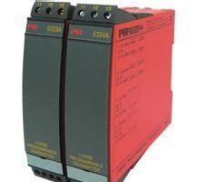 Demodulate and transform back to the original signal or a different signal before isolation, and at the same time isolate the power supply of the isolated signal. Ensure the absolute independence between the converted signal, power supply and ground. There are so many brands of isolators on the market now, and the prices vary. How to choose?
The isolator is located between two system channels. Therefore, when choosing an isolator, you must first determine the input and output functions. At the same time, the isolator input and output mode (voltage type, current type, loop power supply type, etc.) must be adapted to the front-end and back-end channel interface modes. In addition, there are many important parameters such as accuracy, power consumption, noise, insulation strength, bus communication, etc. related to product performance. For example, noise is related to accuracy, and power consumption is related to reliability. These need to be selected carefully by the user. In short, trial use, reliability, and product cost-effectiveness are the main principles for selecting isolators.
Working principle: First, the semiconductor device is modulated and converted, and then the isolation conversion is performed through a light sensor or a magnetic sensor, and then the signal is demodulated back to the original signal before isolation. At the same time, the power supply of the isolated signal is isolated to ensure that the power supply of the converted signal is isolated. Ensure the absolute independence between the converted signal, power supply and ground.
One: Protect the lower-level control loop.
2: Reduce the impact of environmental noise on the test circuit.
Three: Suppress the faithful protection of public grounding, frequency converter, solenoid valve PLC/DCS input and output and communication interface.
The standard series guide rail structure is easy to install and can effectively isolate; the potential between the input, output, solenoid valve and the ground can overcome various high and low frequency pulsation interference of the inverter noise level.
What are the main types of signal isolators?
1) Isolator
In industrial production, in order to increase the load capacity of instruments and ensure that instruments connected to the same signal do not interfere with each other, it improves the performance of electrical installation. It is necessary to collect, amplify, calculate, and perform anti-interference processing on the input voltage, current, frequency, resistance and other signals, and then output the isolated current and voltage signals and safely send them to secondary instruments and PLC/DCS for use.
2) Distributor
Industrial sites generally need to use a two-wire transmission method to control the engineering network. All rights reserved. It must not only provide 24V power distribution for primary instruments such as transmitters, but also collect, amplify, calculate, and perform anti-interference processing on the input current signals, and then output isolated current signals and voltage signals for use by subsequent secondary instruments or other instruments.
3) safety barrier
Some special industrial sites not only require two-wire transmission, but also need to provide power distribution and signal isolation functions. They also need to have safe spark-explosion-proof performance, reliably contain the power supply, prevent ignition between power supply, signal and ground, double limit the signal and power circuit with current limiting and voltage reduction, and limit the energy entering the dangerous place within the safe quota range.
What matters should be paid attention to when installing and maintaining signal isolators?
Due to different manufacturers, the production processes and wiring definitions of isolators are also different, but the use occasions are basically the same, so the protection requirements and maintenance of the products are basically the same.
1. Read the instructions carefully before use.
2. When used as signal isolation, the input terminal should be connected in series to the loop circuit and the output terminal should be connected to the sampling loop.
3. When used as isolated power distribution, the input terminal should be integrated into the power circuit and the output terminal should be connected to the transmitter.
4. If it does not work properly, first check whether the wiring is correct, and pay attention to whether the power supply and polarity are certified. Why do the phenomenon signals received by PLC sometimes have large errors and poor stability?
There are many reasons for this imagination. The potential difference between different instrument signal reference points is an important factor. This difference causes interference currents between instrument signals, resulting in large PLC errors and poor stability. Therefore, it is the best situation for the signals of different equipment and instruments to have a common reference point. The isolator completely isolates the input/output electrically, and the analog interface board on the PLC forms a common reference point, and the problem of ideal installation impedance is solved.
The 4-20mA channel is isolated, and there is no room for power supply in the cabinet. What to do?
A passive signal isolator that can achieve 4-20mA signal isolation without the need for an external power supply. PH1033 is such a product.
There are so many brands of isolators on the market now, and the prices vary wildly. How to choose?
The isolator is located between the two system channels, so when choosing an isolator, you must first determine the input and output functions, and at the same time, adapt the input and output modes of the isolator to the front-end and back-end channel interface modes. In addition, there are many important parameters such as accuracy, power consumption, noise, insulation strength, and bus communication functions that involve product performance. For example, noise is related to accuracy, and power consumption is related to reliability. These need to be chosen carefully by the user. In short, applicability, reliability, and product cost-effectiveness are the main principles for selecting isolators.
The signal from the on-site two-wire pressure transmitter received by DCS is unstable. How to solve it?
Two-wire transmitters are frequently used in the field of industrial automation. Like other industrial field equipment, two-wire transmitters also have problems with interference and anti-interference. According to the DCS simulation board interface mode, select an isolation distributor with different functions. In principle, it is required that it can not only provide isolated power to the transmitter, ensure that each transmitter has an independent power supply, but also isolate the transmitter signal and transmit it to the DCS.
The PLC analog board interface is a two-wire loop power supply, and the signal needs to be isolated. How to choose a product?
The two-wire loop power supply method is a common analog board interface. Products suitable for this interface are called two-wire loop isolation series products. The isolation devices inside this isolation transmitter adopt the transformer method. On the one hand, it transmits signals, and on the other hand, it also transmits the power from the power supply end to the input part, so that various circuits in the input part can work normally. For example, ph2217 and other electrical distribution products.
How many common two-wire distributors are there?
There are two series of commonly used two-wire isolation distributors to choose from. What the two series of products have in common is that they can provide an independent isolated power supply to the two-wire transmitter after isolation from the external power supply: the power distribution of the transmitter depends on the PLC/DCS analog power supplied on site.
Application of safety barrier
The safety barrier originally belonged to the auxiliary unit of the electric unit combination instrument, and its main purpose is the isolation device of the explosion-proof system. The safety barrier isolates and transmits the signal from the dangerous area and outputs the isolated current signal to the safe area. The safety barrier is used in intrinsically safe explosion-proof systems to limit the energy sent to the on-site loop through current limiting and voltage limiting circuits, thereby preventing dangerous energy from non-intrinsically safe circuits from entering the intrinsically safe loop. Safety barriers are widely used in automation systems such as DCS/PLC/PCS in petrochemical and other industries.
Common safety barriers can be divided into Zener type and isolation type according to their structural forms.
Applications of Zener safety barrier:
Quick fuses, current-limiting resistors or voltage-limiting diodes are used in the circuit to limit the input electrical energy to ensure the energy output to the hazardous area. However, due to defects in the principle, the reliability of its application is affected and its scope of application is limited. The reasons are as follows:
1. The installation location must have a very reliable grounding system. The grounding resistance of the Zener safety barrier must be less than 1 ohm, otherwise the safety protection performance will be lost. Obviously, such requirements are very demanding and difficult to guarantee in engineering applications.
2. It is required that the field instruments in the hazardous area must be of isolation type, otherwise the signal cannot be transmitted correctly after the ground terminal of the Zener safety barrier is connected to the earth, and due to the grounding of the signal, the anti-interference ability of the signal is directly reduced and the system stability is affected.
3. The Zener safety barrier has a greater impact on the power supply. At the same time, it is also easy to cause damage to the Zener safety barrier due to fluctuations in the power supply.
Applications of isolation safety barriers:
Adopt a circuit structure that electrically isolates the input, output, and power supply from each other, and at the same time meets the requirements of intrinsically safe energy limits.
1. The three-party isolation method is adopted, so there is no need for system grounding lines, which brings great convenience to design and on-site construction.
2. There is no need to use isolated instruments for on-site instruments in hazardous areas.
3. The signal lines do not need to share the ground, which greatly enhances the stability and anti-interference ability of the detection and control loop signals, thereby improving the reliability of the entire system.
4. The isolated safety barrier has stronger input signal processing capabilities and can accept and process signals such as thermocouples, thermal resistors, and frequencies, which is something that the Zener safety barrier cannot do.
5. The isolation safety barrier can output two mutually isolated signals to provide two devices using the same signal source, and ensure that the signals of the two devices do not interfere with each other, while improving the electrical safety insulation performance of the connected devices.
Therefore, after reviewing the characteristics and performance of zener and isolation safety barriers, it can be seen that the isolation safety barrier has outstanding advantages and is more widely used. In engineering sites with higher requirements, the isolation safety barrier is almost without exception used as the main intrinsically safe explosion-proof instrument. The isolation safety barrier gradually replaces the zener safety barrier.





 Home


