Sharing of cases of gas turbine flow meter failure caused by wiring problems in industrial instrumentation weaknesses
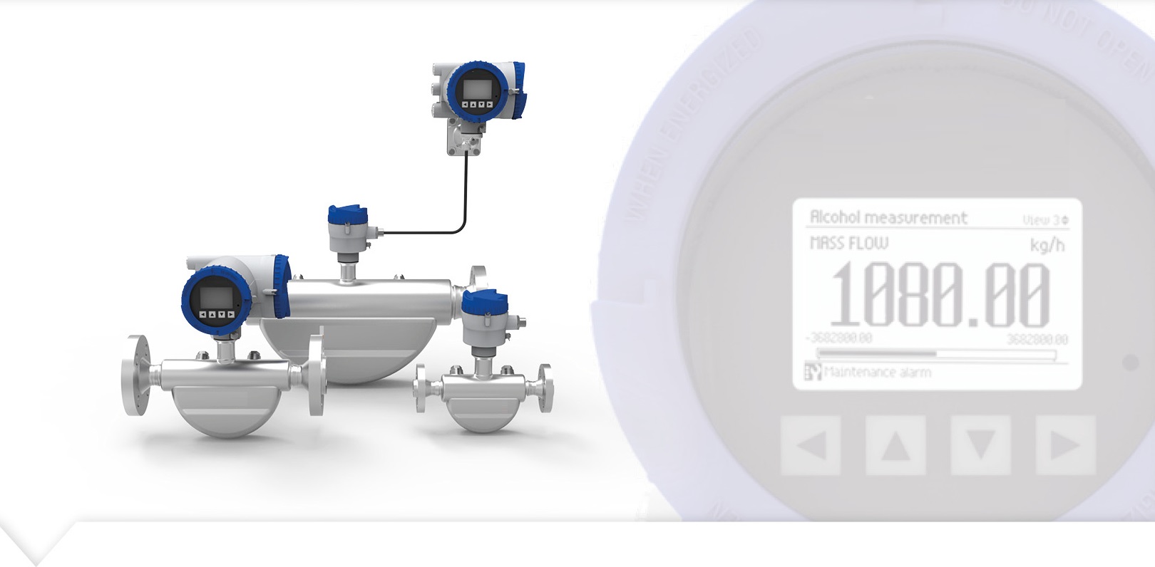
4-20mA, as one of the main output modes of the flow meter, is susceptible to interference, causing fluctuations in the meter's measurement display. Commonly used improvement measures include shielding layers, grounding, barriers, etc., but these improvement measures require high experience of on-site instrumentation personnel. Once a problem occurs during installation, it will not play an anti-interference role, but will further cause other problems.
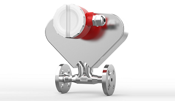
The case I will share with you today is an isolation barrier wiring problem caused by a gas turbine flow meter display failure.
The customer is a combustion equipment company whose role in the process is to measure gas consumption. Customer feedback: When the three-wire current is connected on site, the current output of the instrument does not match the upper level, which is always 10 square meters. The on-site test found that there was no problem with the on-site instrument display and the displayed current, but the upper limit set by the touch screen was the same, that is, the flow rate could not be matched.
Remove the excitation wire and measure normally behind the meter. After wiring, the test circuit current decreases by 0.4ma. There is a problem with the pre-field measurement method, so the measurement is always inaccurate.
After questioning the scene, it was discovered that there were obstacles at the scene. In order to verify whether it is an obstacle problem, the measurement is normal before entering the obstacle. After entering the potential barrier, the current decays to 0.4ma.
Therefore, it is judged that there is a problem with the barrier or connection method, and there is no problem with other two-wire temperature and pressure. The next step is to replace the barrier. We found that the same problem still exists. After checking with the barrier manufacturer, he said he had not encountered this situation. Upon enquiry, it was revealed that the barrier itself did not have 24 volt power. Make sure terminal 1 is negative, terminal 2 is signal, and terminal 3 is 24 volts positive. Field wiring terminals 1 and 2.
As shown in the figure below: Under this wiring method, the current attenuation is 0.4ma. At this time, we know that the barrier itself has a feeder line, so we decided to use the power of the barrier to power the instrument. As shown in the picture below: If the grid is used for power supply, the current flow is normal.





 Home


