Step One: Preparation
The pressure source is connected to the self-made joint through a rubber tube, the balance valve is closed, and the gas line sealing is checked. Then the ammeter (voltmeter) and handheld device are connected to the output circuit of the transmitter, and the calibration is started after power on and preheating. We know that no matter what model of differential pressure transmitter, the positive and negative pressure chambers have exhaust and drain valves or cocks; this provides us with convenience for on-site calibration of the differential pressure transmitter, which means that the differential pressure transmitter can be calibrated without removing the pressure guiding pipe. When calibrating the differential pressure transmitter, first close the positive and negative valves of the three-valve group, open the balance valve, then loosen the exhaust and drain valves or cocks to vent them, and then use homemade joints to replace the exhaust and drain valves or cocks connected to the positive pressure chamber; while the negative pressure chamber remains unscrewed to allow it to vent to the atmosphere.
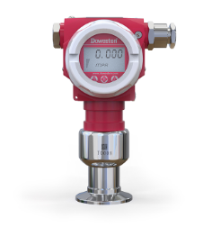
Step 2: Calibration of conventional differential pressure transmitter
First adjust the damping to zero state, first adjust the zero point, then add full pressure and adjust the full range so that the output is 20mA. On-site adjustment is about fast. Here we introduce the quick adjustment method of zero point and range. There is almost no impact on the full scale when adjusting the zero point, but it has an impact on the zero point when adjusting the full scale. Without migration, the impact is about 1/5 of the range adjustment amount, that is, if the range is adjusted upward by 1mA, the zero point will move upward by about 0.2mA, and vice versa.
Step Three: Calibration of the Intelligent Differential Pressure Transmitter
It is not possible to calibrate the smart transmitter using the above conventional method, because this is determined by the structural principle of the HART transmitter. Because between the input pressure source and the generated 4-20mA current signal, the smart transmitter, in addition to machinery and circuits, also has a microprocessor chip to calculate the input data. Therefore, the adjustment is different from the conventional method.





 Home


