The general and special types of electromagnetic flow meter on the market can be classified from different angles. There are many types under each classification. Here are some commonly used classification methods of electromagnetic flow meter:
1. Classification according to output signal connection and excitation (or power supply) connection format
Four-wire electromagnetic flow meter The four-wire system is a four-wire system in which the output signal line and power line (or the excitation wire between the flow sensor and the sensor) of the traditional electromagnetic flow meter are composed of 2 groups of 2 wires each. It is the current main system.
Two-wire electromagnetic flow meter Current field instruments for parameters such as temperature, pressure/differential pressure, flow and level tend to develop as two-wire instruments that share wires for output signals and power supplies. Two-wire instruments do not require mains power supply, and electromagnetic flow meter are often installed in remote places without mains supply. Using two-wire systems can save the cost of mains wiring projects. The design idea of the power supply of the two-wire electromagnetic flow meter is divided into zero signal output current (i.e. 4mA) supply, greater than zero signal output supply and battery (or solar cell) supply. Battery-powered electromagnetic flow meter and electromagnetic water meters are suitable for installation in places where it is difficult to introduce mains power away from urban distribution pools or discharge points after suburban sewage treatment. The battery life of some models of instruments is 1-2 years, and some are as long as 8-10 years.
2. Classification according to assembly methods of sensors and converters
Split type electromagnetic flow meter Split type is the most commonly used form of electromagnetic flow meter. The sensor is connected to the pipeline, and the converter is installed in the instrument room or near the sensor where people can easily access it, tens to hundreds of meters apart. To prevent the intrusion of external noise, signal cables are usually double-shielded. When measuring liquids with low conductivity and the distance exceeds 30m, in order to prevent signal attenuation caused by partial capacitance of the cable, the inner shield is also required to be connected to a shield driver with a low impedance source at the same potential as the core wire. The isolated converter can be far away from the harsh environment on site, making it easier to inspect, adjust and parameterize electronic components.
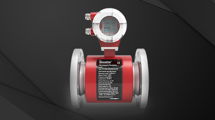
Integrated electromagnetic flow meter sensor and converter are assembled together to directly output a DC current (or frequency) standard signal, which actually becomes an electromagnetic flow transmitter. The integrated type shortens the connection length of the signal line and the excitation line between the two, and makes them external and hidden inside the instrument, thereby reducing signal attenuation and space electromagnetic wave noise intrusion. The same measuring circuit can measure liquids with lower conductivity than the remote type. The wiring of signal lines and excitation lines is eliminated, and electrical connections are simplified. The price and installation cost of the instrument are relatively cheap, and it is mostly used in small-diameter instruments. With the commercialization development of two-wire instruments, integrated instruments will develop rapidly. However, if it is installed in an inaccessible place due to pipeline layout restrictions, maintenance will be inconvenient. In addition, the electronic components of the converter are installed on the pipeline, which will be greatly restricted by the fluid temperature and vibration of the pipe.
3. Classification according to the connection method between flow sensor and pipeline
Flange connection Flange connection is a traditional connection method. There are connecting flanges at both ends of the sensor, which are fixed with bolts to the pipe flange. It can be installed in one direction. Large-diameter sensors all use this connection method. The volume and weight are larger than the clamping connection method. The International Organization for Standardization has formulated standards (ISO 13359; 1998) to unify the length between the two flange surfaces of the electromagnetic flow meter from DN15 to 600mm.
Flange clamping connection Flange clamping connection is a connection method developed in recent years. The sensor itself has no flange and is clamped between the two flanges of the pipe with a longer bolt to connect to the piping system. This type of sensor is small in size and light in weight, and has strong adaptability to different pressure specifications and standard piping system flange hole spacing; however, it is only suitable for smaller pipe diameters (less than 200mm) and can withstand low liquid working pressures.
Clamp connection The clamp connection enables quick disassembly and installation, which facilitates daily and frequent cleaning.
Threaded connection This type of instrument is mostly used in industries such as medicine and food, as well as in places such as pharmaceutical proportioning and injection. Threaded connections are also widely used in high-pressure water injection or cement slurry flow measurement above 16 to 25MPa in petroleum, geological exploration, etc., and the thread shape is trapezoidal.
4. Classification according to whether the flow sensor electrode is in contact with the liquid being measured
Contact electrode The electrode in contact with the liquid is the traditional structure of EMF, usually a pair of electrodes, and two pairs of electrodes are used in the large-diameter instrument industry. Non-full tube EMFs also use 3 pairs of motors or strip electrodes.
Non-contact electrode The large-area electrode is close to the outer surface of the lining (or insulated measuring tube) and detects the flow signal by capacitive coupling. The electromagnetic flow meter that can measure the capacitance detection method of the contact type electrode is called a capacitive electromagnetic flow meter. The preamplifier is placed in the sensor and relies only on the electrodes. The excitation frequency is higher than the usual EMF, which is 50/2Hz, and some even exceed 100Hz. This type of instrument will not produce electrode surface effect noise such as electrode passivation, oxidation and catalytic action, and there is also no flow noise and slurry noise. Even if the inner surface of the lining is covered with a non-conductive layer such as grease or a thin insulating structural layer, the measurement will not be affected; however, if the covering layer is a conductive film, the meter will have no indication. Some foreign instrument manufacturers call this type of instrument an electrodeless electromagnetic flow meter.





 Home


