Clamp-on Ultrasonic Flow meter Installation Guide
Clamp-on ultrasonic flow meter is mainly used to measure the flow rate of clean water in pipelines. Due to its easy installation and high measurement accuracy, it is used in flow measurement in various industries.
The installation mainly consists of the following steps:
1. Determine the installation location
2.Set instrument parameters
3. solidFixed ultrasonic flow meter probe
4. Debugging flow meter parameters
5. Fixed flow meter host
1. Select installation location
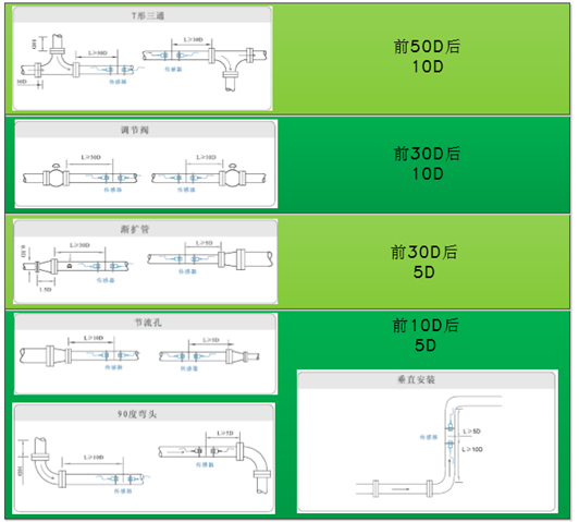
Installation location requirements: (1) The pipe must be full; (2) A long enough straight pipe section (refer to the figure below).
2. Parameter settings
(1) Measure the outer circumference of the pipe and calculate the outer diameter.
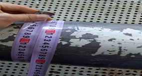
Outside diameter measurement
(2) Power on the host, the power supply range is 10~36VDC, and connect to the DC+ and DC- terminals on the meter.
(3) Press the "menu" key, enter 11, press the "Enter" key, then use the keyboard to enter the outer diameter of the pipe, and press the "Enter" key when the input is complete.
(4) Press the "﹀" key, press the "Enter" key and then use the keyboard to enter the pipe wall thickness. Press the "Enter" key when the input is complete.
(5) Press the "﹀" key and press the "Enter" key to select the pipe material by pressing "﹀" (the words after 0, 1, and 2 represent carbon steel, stainless steel, and PVC materials respectively), and press the "Enter" key when the input is completed.
(6) Press the "﹀" key, press the "Enter" key, and select the sensor type by pressing "﹀". Here, select "0", external clamp type. Press the "Enter" key after input is completed.
(7) Press the "﹀" key, press the "Enter" key, and select the installation method by pressing "﹀". Generally, the "V" or "Z" method is selected for installation. Press the "Enter" key after completing the input.
(8) Press the "﹀" key to display the installation distance, which can be considered as the length of the pipe between the two sensors.
Three. Installation steps
(1) Determine the installation points of the two probes based on the installation distance calculated by the instrument host and mark them.
(2) Polish the installation points clean: PVC and stainless steel pipes should be scrubbed clean of dust, mud, etc. on the surface of the pipes, and carbon steel pipes should be polished off anti-rust paint, rust, etc. to make their contact surfaces clean and smooth.
(3) Install the flow meter probe according to the marked position. The probe with the red mark on the line is installed in the upstream direction of the flow direction in the pipe, and the blue mark is installed in the downstream direction.
(4) After the installation is completed, connect the wires as shown below.
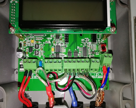
Wiring Diagram
(5) Press the "menu" key, enter 90, check the corresponding values of UP, DP, and Q, and adjust the left and right alignment of the probe so that these three letters are greater than 70.
(6) Press the "menu" key and enter 91 to view the numerical percentage on this interface. It can be modified by adjusting the distance between the probes to make it reach 97%~103%.
(7) After debugging is completed, press "menu" and enter 00 to return to the measurement interface.
Four. Installation tips and precautions
(1) The measurement point should be a uniform straight pipe section within 10 times the diameter (10D) upstream and 5 times the diameter (5D) downstream. There should be no valves, elbows, diameter reduction and other devices that interfere with the flow field within this range. It is recommended that the length of the straight pipe section be as shown in the table below.
(2) On a horizontal pipe section, the sensor should be installed at the 9 o'clock and 3 o'clock positions of the pipe, and should avoid the 6 o'clock and 12 o'clock positions to avoid signal attenuation caused by sediment at the bottom of the pipe or bubbles and air pockets in the upper part of the pipe.
(3) ZHow to determine the installation point on the other side: Use the original hoop (or other(Other strip-like objects with even edges), wrap around the pipe and tighten it so that the edges of the overlapping parts are aligned. Use a marker to draw a circle along the edge of the hoop. Find the installation point on one side, then use a tape measure to measure the arc distance of half the circumference, and mark it, which is the base point on the other side. Measure an installation distance from the base point, which is the installation position on the other side.
VFrench installation renderings
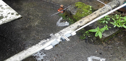
ZFrench installation renderings
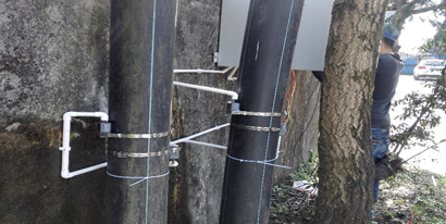
(4) Installation instructions, whether it is V method or Z method installation, require alignment, that is, the center line of the two probe fitting surfaces must be parallel to the center line of the pipe.
(5) If conditions permit during installation, the valve and motor can be closed so that the pipe is filled with water but does not flow, which makes debugging easier.





 Home


