A membrane in which the physical properties of the membrane change as the membrane deforms (e.g., a strain gauge changes as resistance changes).
Pressure Transmitter
Transmitter used to convert the pressure to be measured into a defined or standardized analog and/or digital output signal.
Pressure Sensor
Pressure sensors have process and electrical connections (e.g., connectors) but do not convert pressure into a standardized electrical signal like a pressure transmitter.
Pressure measurement type
differential pressure measurement
Measurement of the pressure difference between two different pressures.The measuring instrument has two pressure connections.
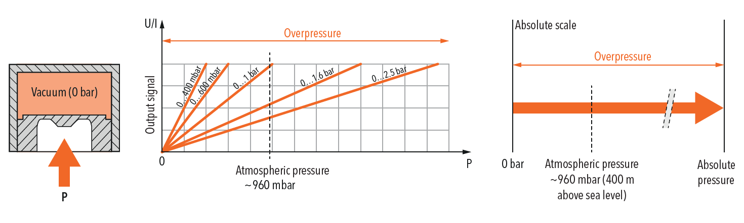
Absolute pressure measurement
The measurement is always a deviation from absolute zero (vacuum).
For example 4 mA = 0 bar (=vacuum); Zero point (ZP): 0 bar
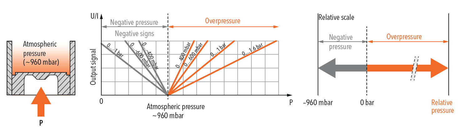
Relative pressure measurement (DIN 16086: Overpressure)
The measurement is always a deviation relative to the current absolute atmospheric pressure.
For example, 4 mA = 960 mbar (=atmospheric pressure);Zero point (ZP): 0 bar
Main features
nominal pressure measuring range
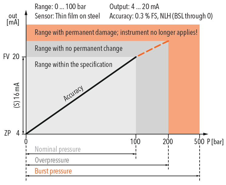
The range between the upper and lower limits of the measured size (operating pressure).The specified accuracy remains within this range.
Measuring Range
The algebraic difference between the upper and lower limits of a measurement range.
Overpressure (maximum working pressure)
The maximum pressure specified by the manufacturer and the maximum temperature the pressure transformer is designed for.The pressure transformer can be loaded to this pressure without the guaranteed metering performance changing after returning to the measuring range.However, in the range between nominal pressure and overpressure, there is no longer a clear connection between pressure and output signal.
Burst Pressure
Pressure value (static) at which the measuring instrument is permanently damaged.The instrument can withstand pressures up to this value without rupture and without leaking any measuring medium.
Accuracy
Typical accuracy
(Typical value) usually corresponds to the 1-sigma value of the normal distribution, i.e. approximately.68.3%.Typically, more than 75% of all Trafag instruments achieve this typical measurement value.
Maximum accuracy
(Maximum) 100% of all instruments achieve this maximum measurement value.
Nonlinearity
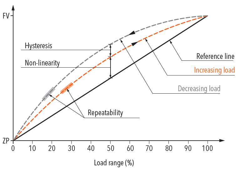
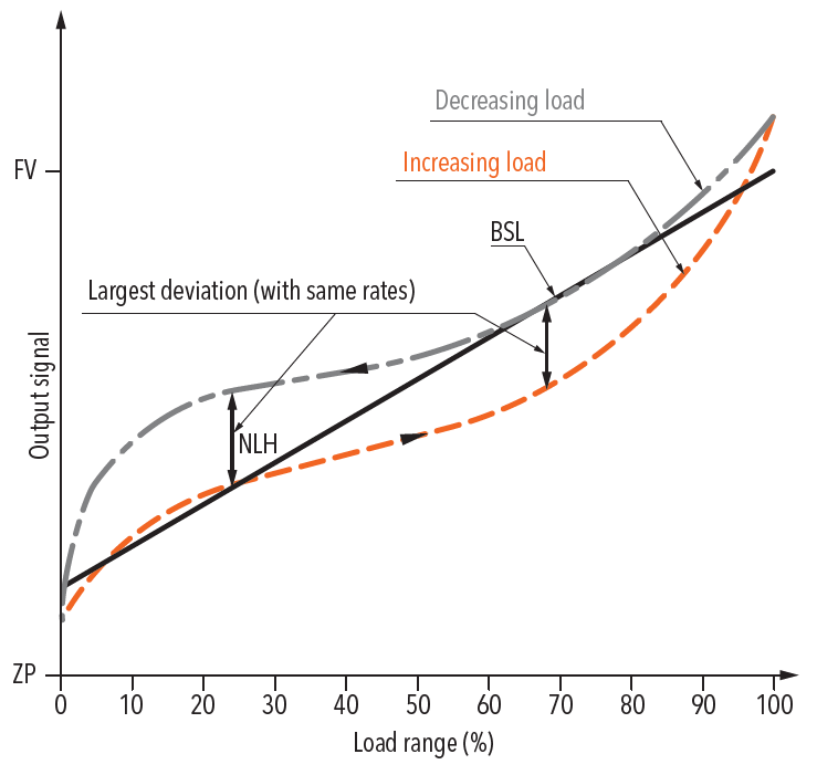
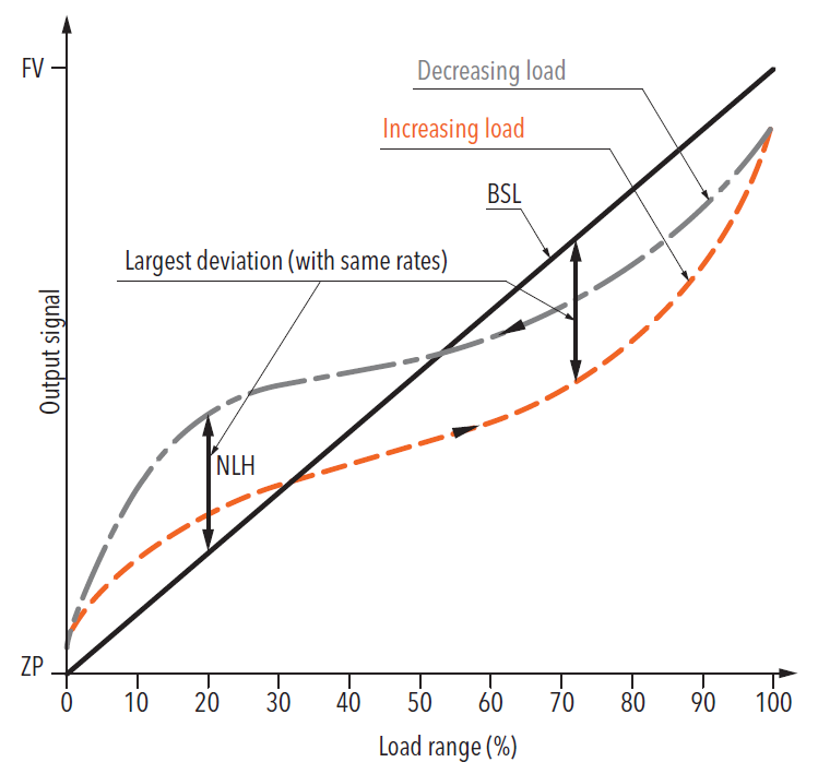
Maximum deviation from the effective characteristic line of the ideal reference line.The baseline can be defined as the limit point adjustment, BSL or BSL to 0.
BSL best straight line
The reference line adjusted according to the BSL or minimum value should be placed in such a way that the maximum positive and negative deviations are as small as possible.
BSL to zero
As an additional requirement for minimum adjustment, BSL to zero (also BSL/0) must pass directly through zero or the origin.
Nonlinearity adjusted according to limit points
Reference lines pass through the start and end points of the breakline.Nonlinearity represents the maximum deviation from this line.
Hysteresis
Property of an instrument that produces different output values relative to its input values, depending on the valid direction in which the input values are created (according to IEC 61298-2).
Pressure hysteresis
The difference between two measurements at the same pressure in the direction of increasing and decreasing pressure.
Temperature hysteresis
The maximum change in the zero point and output range of the pressure signal after a specified temperature cycle within the operating temperature range.
NLH nonlinearity and hysteresis
Maximum deviation from the ideal characteristic line (BSL, BSL/0 or limit point).In pressure measuring instruments, nonlinearity and pressure hysteresis are given together at constant temperature.
Accuracy DIN 16086: Measurement deviation
The accuracy expressed in standard DIN 16086 is subject to measurement deviations (at a reference temperature of 25°C), including all deviations due to non-linearity, hysteresis, non-repeatability, errors in zero point (start of the measuring range) and span (end point). measurement range) error.Zero and span errors also include the measurement uncertainty of the configuration ensemble.
Repeatability DIN 16086: Non-repeatability
The deviation of an output signal from the same input signal under the same (determined) application conditions.
Temperature coefficient TC
Temperature changes cause changes in the zero and span measurements.
Long term stability Long term drift
Changes in accuracy due to aging under certain reference conditions over a certain period of time (usually 1 year).
TEB total error band
Total error (square root of the sum of squared deviations) due to measurement deviation (accuracy) and temperature effects (temperature coefficient TC).Usually the temperature influence range given in Trafag's information is larger than the range given by the standard (-10... +60°C).Although DIN 16086 continues to improve long-term stability for another year, the information from Trafag is still subject to factory conditions for obvious reasons.
Scale accuracy
For voltage regulators: deviations caused by manual switching point adjustment using the display (scale).
Electrical data
Output
Sends an electrical signal that measures the dimensional value for further processing.
Rise time (step response)
The time it takes for the output signal to increase from 10% to 90% of the final value of the pressure change after a drastic change in pressure.
Zero point ZP
Output signal (Pmin) in no-pressure state, e.g. 4 mA at 0 bar (Pmin)
Final valueFV
Output value for the maximum pressure value in the nominal pressure range (Pmax), e.g. 20 mA at 100 bar (Pmax).
Span S
Final Value (FV) – Zero Point (ZP) = Span (S), For example, span (S) = (FV) 20 mA - (ZP) 4 mA = 16 mA
Switch differential pressure
The range in which the microswitch in the voltage regulator opens and closes. For example X... X = adjustable value X – X = non-adjustable value;Proportional to nominal pressure X = fixed value
Voltage limiter
Pressure stabilizer with manual microswitch reset.
Environmental conditions
Medium temperature
Properties of an instrument designed to function in an environment with electromagnetic interference and not unduly affect that environment (to which other equipment also belongs).
ambient temperature, operating temperature
The temperature range within which the measuring instrument meets its specifications.Because the electronics in some instruments are more sensitive to temperature than the sensor, the maximum ambient temperature of the instrument is lower than the allowed medium temperature.
Storage temperature
The temperature range within which a measuring instrument can be stored or transported without permanently changing the measuring characteristics.
Protect
Moisture- and dust-proof cover, IP-rated, in accordance with EN 60529.
Burst
Unaffected by periodic, rapid, brief electrical disturbances
EMC protection
EMC electromagnetic compatibility
Properties of an instrument designed to function in an environment with electromagnetic interference and not unduly affect that environment (to which other equipment also belongs).
Admission
Not affected by external electromagnetic interference.
Emissions
Interference caused by electromagnetic interference.
Surge
Unaffected by unipolar surge voltages caused by surges caused by switching operations and lighting.
Burst
Unaffected by periodic, rapid, brief electrical disturbances
Our experts are ready to helpWherever you are, DOWESTON's experienced engineering team is ready to support your product selection and applications - contact us today!
Tell us about your measurement task and we will help with product selection and technical questions.info@doweston.com
We value your privacy!
We and our partners use cookies and similar technologies to process personal data (such as IP address or browser information) in order to personalize the content and advertising shown to you. This helps us display more relevant content and improve your browsing experience. We also use it to measure results and tune website content. Because we value your privacy, we are asking for your permission to use these technologies. You can change or withdraw your consent at any time by clicking the settings button in the lower-left corner of the page.





 Home