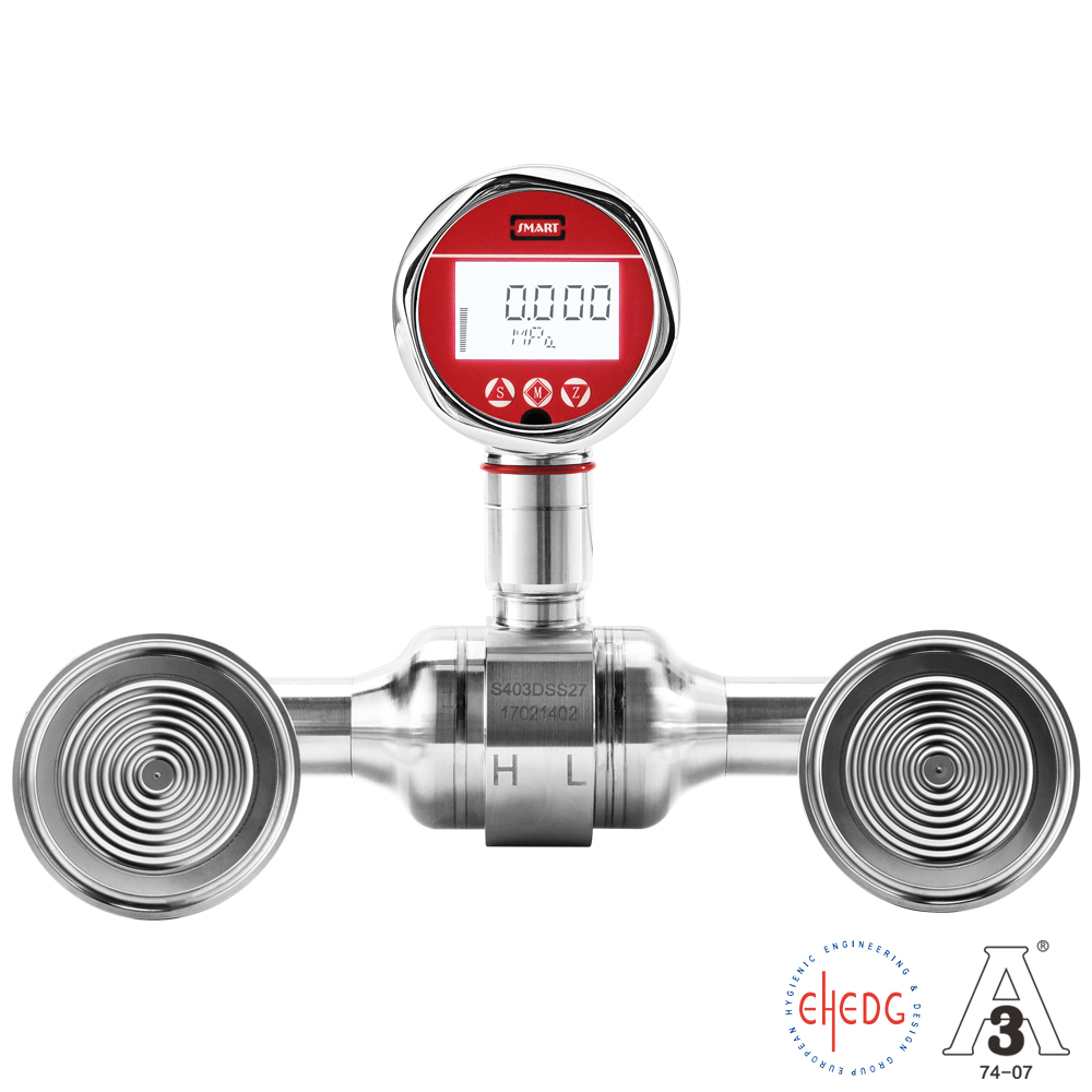
A medical water for injection storage tank has two sets of double-flange diaphragm sanitary level gauges used to measure water for injection. The temperature is 90°C, the measuring range is 2 meters, and the capillary tubes are one meter each. 4-20mA is used for signal acquisition.
When the double flange diaphragm level gauge is actually used, the level gauge always has a zero point drift ranging from 20 to 37 mm when it is drained. It needs to wait until the equipment is completely cooled before it will basically return to zero, and this offset tends to amplify. It is only 20mm at the beginning, 30mm at the back, and the maximum feedback is 37mm. Comprehensive analysis found that the height and liquid level sensors of the liquid level gauge work in different temperature zones when the equipment is emptying. How to eliminate the temperature difference caused by the different temperatures? The liquid level gauge needs to wait until the equipment cools down to return to zero. Can the zero reset process be accelerated and return to zero quickly? How to eliminate the zero point temperature drift problem?
With such questions, we began to seek optimization and solutions.
We thought about it as follows:
1. Is it possible to suppress this temperature drift by enlarging the sanitary chuck and filling it with industrial high-temperature silicone oil? Currently, the 50.5 chuck is filled with sanitary silicone oil.
2. Can zero-point calibration be performed to eliminate temperature drift at high temperatures when the liquid level has been emptied but the equipment is in the high temperature zone when it was just emptied? Is it feasible to reset the PV when emptying is confirmed but the equipment is at high temperature?
3. Can it be optimized through external cooling?
Results of analysis:
1. On the one hand, we use materials with less impact on temperature. We replace the original hygienic silicone oil with a temperature resistance of -10~180 to high-temperature silicone oil of 0-315°C, and continue to use the current stainless steel diaphragm and stainless steel pipe.
PS 1: The currently used Tri-Clamp 2" connector is already the largest connector except the flange. Even if the flange-type connector is replaced, the fixed component will only increase, but the size of the contact surface will remain the same. In addition, adding too many connectors will heat the components due to the continuous high temperature of the equipment, resulting in slower heat dissipation.
2. In view of this temperature drift, the sensor under the display meter is actually working under normal temperature conditions, and its temperature compensation only compensates for the influence of the ambient temperature of the body.
However, the remote transmission system is in direct contact with the medium and cannot apply temperature compensation. According to comprehensive analysis, the deviation comes from the fact that the upper sensor is cooled first, and the bottom sensor is cooled later, resulting in a zero point error in the sensor components and physical pressure transmission due to different heating. My solution to this problem is to clear the PV immediately once the discharge is completed under normal discharge conditions to eliminate the pressure difference between the high and low pressure ends caused by the thermal expansion of the bottom pressure sensor due to thermal expansion and contraction of the bottom.
PS 1: This will have a small disadvantage, that is, after the equipment is completely cooled, the displayed value of the liquid level gauge may show a negative number, such as -30mm, but the actual output current is still 4mA because the PV has been calibrated.
PS 2: Another way is to use a Modebus RTU/RS-485 sensor to perform PV zero point control while collecting. If allowed, install a liquid level switch at a low liquid level. When the liquid level switch is triggered normally, the control system device automatically sends a signal to perform a PV zero reset.
PS 3: Install a temperature sensor at the low liquid level measurement point. After determining a linear relationship between time and temperature through the temperature collected by the temperature sensor, the temperature offset is compensated on the acquisition system. The profit is 35mm when the temperature is 90°C, 20mm when the temperature is 60°C, 10mm when the temperature is 45°C, and there is no compensation within the temperature of 30°C.
3. The main reason for the inconsistent zero point is that the temperature drops slowly. Is it possible to perform external cooling, such as spraying, blowing to cool down, or using a cooling component to add a cooling component to the low liquid level end to improve the cooling efficiency.
Write at the end
The temperature drift of the sensor will be affected by changes in ambient temperature, vibration, displacement of the installation position, etc. Even in normal temperature areas, regular zero-point calibration of the instrument is necessary. Many times, vibration, stress, seasonal changes, and environmental changes generated by production may weakly affect the sensor, which is why PV clearing is necessary. The sensor's zero offset amplification may be the comprehensive result of these multiple factors. In actual applications and normal maintenance, you don't need to worry too much.
Regular PV clearing is necessary.





 Home


