





 Home
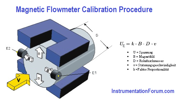
As the fluid passes through the meter's magnetic field, it acts as a conductor. The change in electrical potential varies directly with the fluid velocity.
Input and output standards
Disconnect the flow tube from the transmitter. an electromagnetic flow meter 25The calibrator simulates the signal provided by the electrodes in the flow tube. The operating voltage and frequency range of the calibrator must match the operating voltage and frequency range of the electromagnetic flow meter. Use the calibrator range switch to select the maximum output signal.
Signal options include 5, 10 or 30 mV AC. Magnetic flow meter calibrators have predetermined test points, so the percent output knob is used to set each output for a five-point check. Since the output is in milliamps, a milliammeter is the appropriate output measurement standard for this calibration setup.
Overview of flow measurement categories for liquids and gases
No one measurement technology is suitable for every industry, so you can choose the right flow meter from our comprehensive product range to meet your process measurement and control needs.
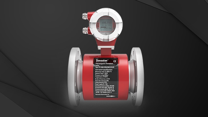
Electromagnetic Flow MeterMature flow measurement technology for measuring various conductive liquids in various industries | 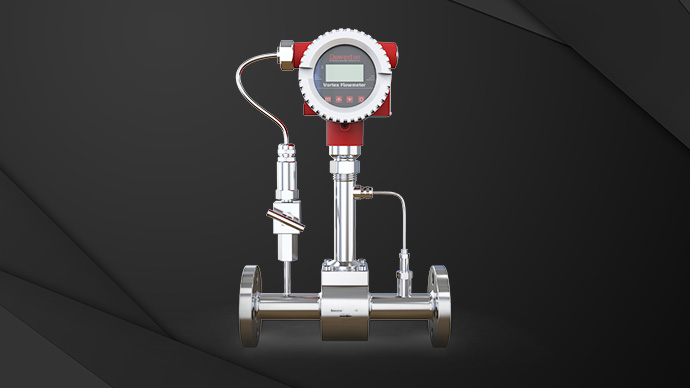 Vortex Flow Meter |
Turbine Flow Meter |
Calibration-Five point check
Start calibrating the electromagnetic flow meter 23, calculate the input signal value. The input signal is equal to the upper range multiplied by the calibration factor and the phase band factor. These values are shown on the instrument's data plate.
Input signal = upper limit x calibration factor x phase band factor
Record the output value at each test point and use this data to determine whether the instrument is within the manufacturer's specifications.
The following formula describes whether the error range is within the manufacturer's specifications:
Accuracy = (deviation/span) * 100
Deviation = expected value – actual value
Zero the instrument at the lowest point of its range by turning the zero screw until the instrument reads correctly. Then adjust the span, and then, since zero and span often interact, verify both until no further adjustments are needed.
To end the calibration, recheck the high-end and low-end readings to verify that the instrument has been calibrated correctly.


