When an electrical conductor moves perpendicular to a magnetic field, a voltage is induced in the conductor that is perpendicular to both the lines of magnetic flux and the direction of motion. This phenomenon is called electromagnetic induction, and it is the basic principle on which all electric generators work. In a generator mechanism, the conductor in question is usually a coil (or set of coils) made of copper wire. However, there is no reason why conductors have to be made of copper wire.
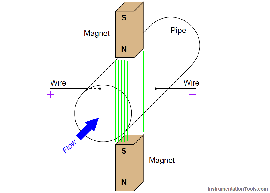
Any conducting substance in motion is enough to electromagnetically induce a voltage, even if the substance is a liquid. Therefore, electromagnetic induction is a suitable technology for the measurement of liquid flow. In reality, only liquid flow can be measured using this technique. The gas must be superheated to a plasma state before it can conduct electricity, so electromagnetic flow meters cannot be used with most industrial gas flows. Consider water flowing through a pipe with a magnetic field passing perpendicularly through the pipe.
DOWESTON sales engineers provide you with high-precision flow meters for measurement and calibration
The direction of liquid flow is cut vertically by the magnetic field lines, creating a voltage along an axis perpendicular to both.
Metal electrodes facing each other in the tube wall intercept this voltage, making it readable by electronic circuits.
The voltage induced by the linear motion of a conductor through a magnetic field is called kinematic EMF, and its magnitude is predicted by the following formula (assuming perfect perpendicularity between the direction of velocity, the direction of the flux lines, and the axis of the voltage measurement):
ε=
Blv
Among them, Ε = motion electromotive force (volts) B = Magnetic flux density (Tesla) L = length of conductor passing through magnetic field (meters) V = velocity of conductor (m/s)
Assuming a fixed magnetic field strength (constant B) and an electrode spacing equal to a fixed diameter of the pipe (constant l = d), then the only variable that can affect the magnitude of the induced voltage is the velocity (v).
In our example, v is not the velocity of the wire segment, but the average velocity of the liquid stream (v). Since we see that this voltage will be proportional to the average fluid velocity, it must also be proportional to the volumetric flow rate, since the volumetric flow rate is also proportional to the average flow rate.
So what we have here is a flow meter based on electromagnetic induction. These flowsThe meter is often called an electromagnetic flow meter or simply a MAGFLOW meter.
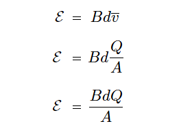
We can state the relationship between volumetric flow (Q) and kinematic EMF (ε) more precisely by algebraic substitution. First, we will write the formula relating volumetric flow rate to average velocity, and then process it to find the average velocity:
Q = average
Q / A = v
Next, we restate the equation of motion electromotive force and then replace v with Q/A to derive the equation relating the motion electromotive force to volume flow (Q), magnetic flux density (B), pipe diameter (d), and pipe area (A):
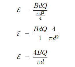
Since we know this is a circular tube, we know that area and diameter are directly related to each other by the equation A = πD 2/4.
Therefore, we can replace this definition of area with the last equation to arrive at a formula with one fewer variable (only d, instead of d and A):
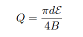
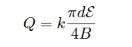
If we wish to have a formula that defines the flow Q of moving electromotive force (ε), we can simply manipulate the last equation to solve for Q:
This formula can only successfully predict traffic if it is absolutely perfect. To compensate for unavoidable imperfections, a "constant of proportionality" (k) is usually included in the formula:
Among them, Q = volumetric flow rate (cubic meters per second) Ε = motion electromotive force (volts) B = Magnetic flux density (Tesla) D = flow tube diameter (meters) K = constant of proportionality
Note the linearity of this equation. Nowhere in the equations of the electromagnetic flow meter do we encounter powers, roots, or other nonlinear mathematical functions.
This means that no special characterization is required to calculate the volumetric flow rate.
See also: Electromagnetic flow meter animation
This formula must satisfy some conditions in order to successfully deduce the volumetric flow rate from the induced voltage:
The liquid must be a reasonably good conductor of electricity (note: it is OK if the conductive fluid contains some non-conductive solid matter; the conductive fluid surrounding the non-conductive solid matter can still provide electrical continuity between the electrodes required for sensing)
The pipe must be completely filled with liquid to ensure contact with both probes and to ensure flow through the entire cross-section of the pipe
Flow tubes must be properly grounded to avoid errors caused by stray currents in the liquid
The first condition can be met by carefully considering the treatment fluid before installation. The electromagnetic flow meter manufacturer will specify a minimum conductivity value for the liquid to be measured.
The second and third conditions can be met by properly installing the electromagnetic flow tube in the pipeline. The flow tube must be completely filled (no air pockets) during installation.
Flow tubes are usually installed with the electrodes crossing each other horizontally (never vertically!), so even a momentary air bubble does not destroy the electrical contact between the electrode tip and the liquid flow.
Electromagnetic flow meters have several advantages over other types of flow meters. Since the induced voltage is only proportional to the vertical velocity of the conductor, in this case the velocity of the fluid along the centerline of the flow tube, they are fairly tolerant to vortices and other large-scale turbulent behavior.
In this way, the electromagnetic flow meter does not require as long upstream and downstream straight pipes as the orifice plate, which is a great advantage in many piping systems.
Typical upstream straight pipe requirements are 5 diameters and downstream straight pipe requirements are 3 diameters.
Additionally, the full opening of the electromagnetic flow meter tube means there is absolutely no way to restrict flow, resulting in extremely low permanent pressure loss.
The absence of any obstructions in the fluid flow path means that the electromagnetic flow meter is quite tolerant to solids in the liquid flow, making it ideal for measuring process liquids such as wastewater, slurry, wood pulp, and food products that may clog other types of flow meter.
In fact, for this reason, electromagnetic flow meters are the primary flow meter technology used in the wastewater, wood pulp, and food processing industries.
The conductivity of the treatment fluid must meet certain minimum values, nothing more. Surprisingly to some technicians, changes in a liquid's conductivity have little effect on flow measurement accuracy.
It's not as if doubling the conductivity of the liquid will result in a doubling of the induced voltage! The kinematic electromotive force is strictly a function of physical size, magnetic field strength, and fluid velocity.
A liquid with poor conductivity will have a greater resistance in a voltage measurement circuit than a liquid with good conductivity, but this doesn't make much sense since the input impedance of the detection circuit is very high.
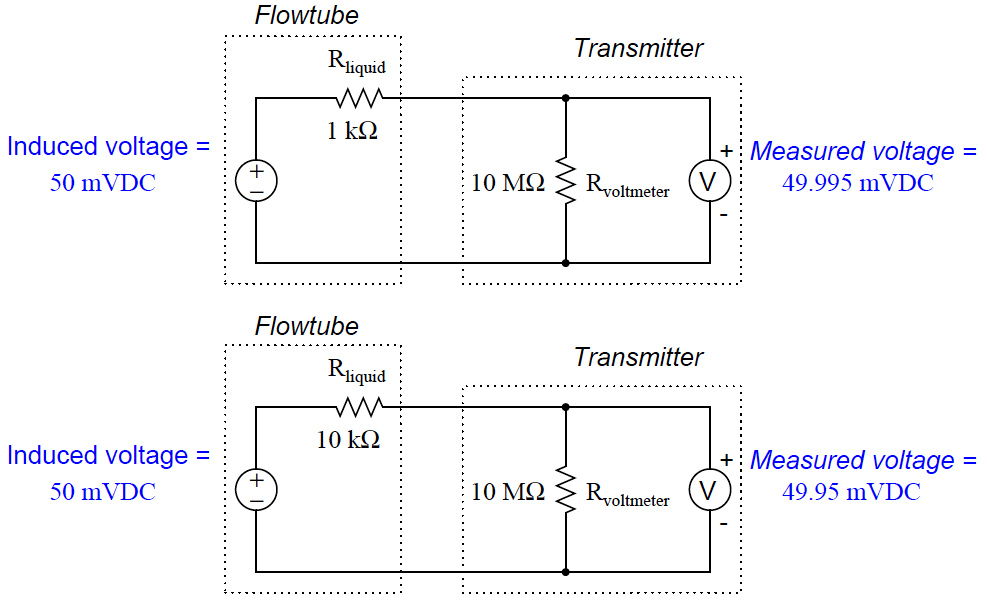
The effect of liquid conductivity on flow meter operation can be modeled by the following DC circuit:
Here, a tenfold (an order of magnitude) change in the liquid resistance has little effect on the measured voltage (49.995 mV vs. 49.95 mV) because the flow transmitter's voltage-sensing electronics have such a high input impedance.
The liquid's equivalent resistance must significantly exceed the value shown in this example before it can have a significant impact on flow measurement accuracy.
In fact, the only problem with electromagnetic flow meters is that the fluid has negligible conductivity.
These fluids include deionized water (such as steam boiler feed water, ultrapure water used in pharmaceutical and semiconductor manufacturing) and oils. Most aqueous (water-based) fluids will work fine with magnetic flow meter.
Proper grounding of the flow meter is very important for electromagnetic flow meter. The motion EMF produced by most liquid flows is very weak (1 millivolt or less!) and therefore easily masked by noise voltages generated by stray currents in the pipe and/or liquid.
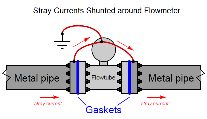
To solve this problem, electromagnetic flow meters are usually equipped with a grounded conductor to shunt (bypass) the stray current around the flow tube, so the only voltage intercepted by the electrode will be the moving electromotive force caused by the liquid flow, rather than the voltage drop caused by the stray. The resistance of an electric current through a liquid.
Electromagnetic flow tube
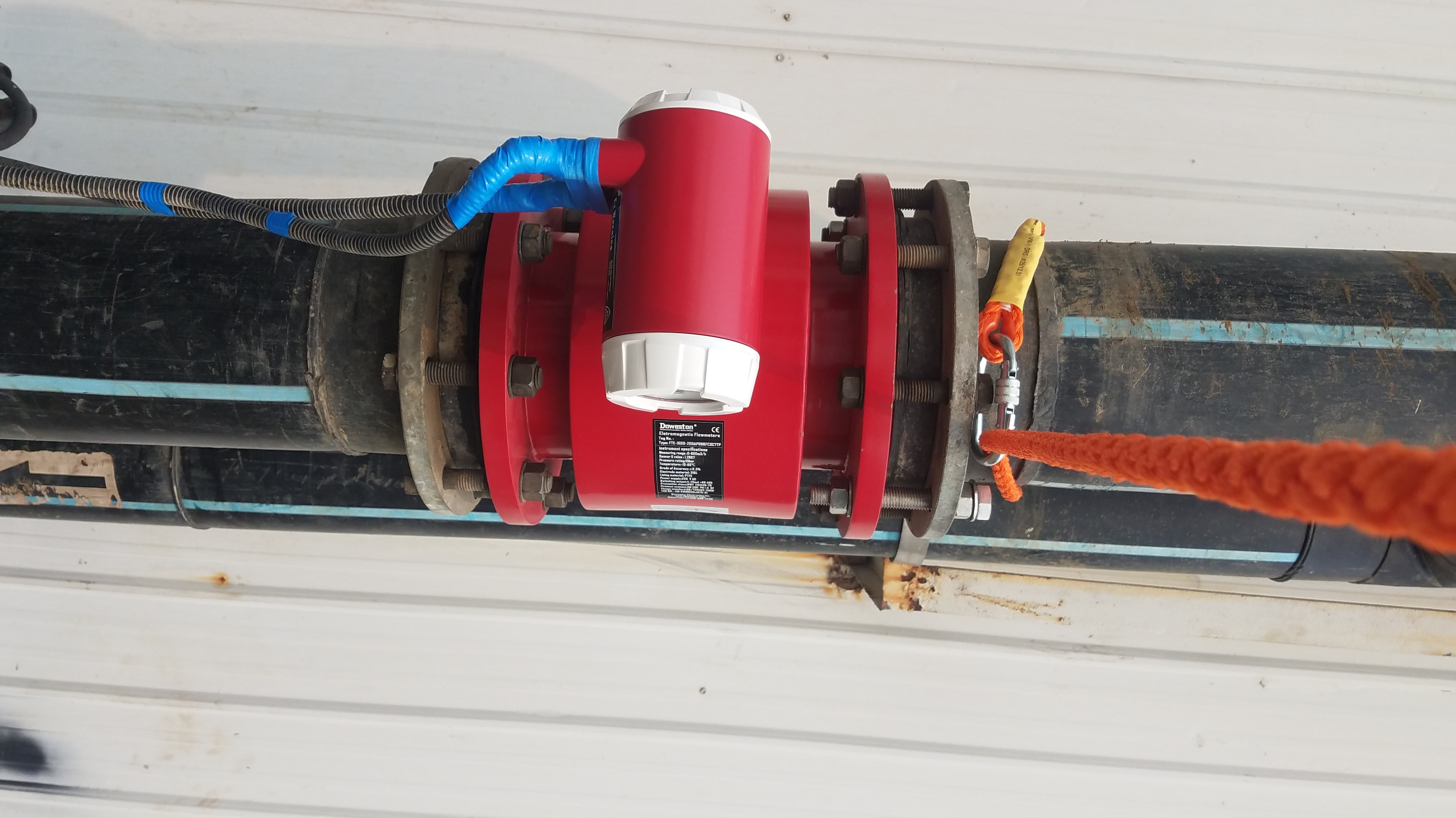
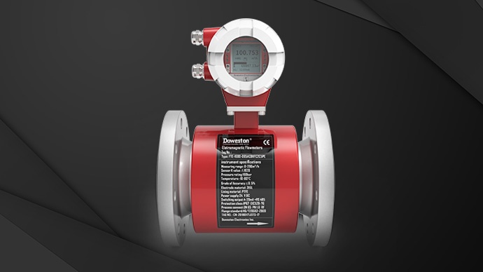
The picture below shows a Doweston large diameter electromagnetic flow tube, with two braided wire ground straps clearly visible:
NOTE: Braided conductors do a better job of shunting RF current because at very high frequencies the skin effect makes the conductor's surface area larger than its cross-sectional area.
Note how the two ground straps connect to a common connection point on the flow tube housing. When flow tubes are installed in a production line, this common connection point should also be connected to functional ground.
On this particular flow tube, you can see a stainless steel grounding ring on the surface near the flange that is connected to one of the braided grounding straps.
There is an identical ground ring on the other flange, but you can't see it in this photo. These rings are made of plastic in pipes or tubesA device that provides electrical contact with a liquid in a device that is metal but lined with plastic to prevent corrosion.
If the pipe connected to the flow tube of the magnetic flow meter is conductive (such as metal), grounding can be achieved by connecting the flange and ground strap of the metal pipe to a common ground point on the body of the flow tube:
Grounding of the pipe flange will be meaningless if the pipe connected to the flow tube is non-conductive (such as plastic) or conductive with an insulating bushing (such as a metal pipe with a plastic bushing).
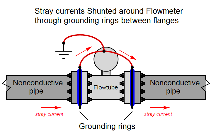
For flow tube grounding to be effective, the ground conductor must have electrical continuity with the fluid itself.
Special grounding rings can be sandwiched between the flanges of non-conductive pipe to provide an electrical contact point to the fluid.
Then, connect these ground rings, along with ground straps, to a common ground point on the flow tube body as follows:
Some electromagnetic flow meter have the signal conditioning electronics located integrally in the flow tube assembly.
Overview of flow measurement categories for liquids and gases
No one measurement technology is suitable for every industry, so you can choose the right flow meter from our comprehensive product range to meet your process measurement and control needs.
Other electromagnetic flow meters have separate electronics and flow tube assemblies connected together by shielded cables.
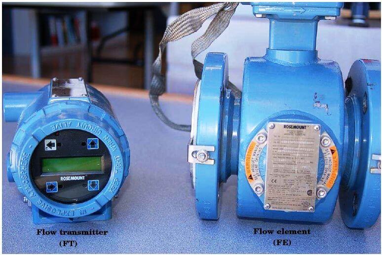
In these installations, the electronic component is called the flow transmitter (FT), and the flow tube is called the flow element (FE):
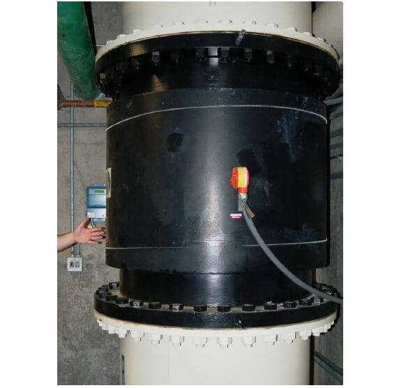
The next photo shows a huge (36-inch diameter!) electromagnetic flow element (black) and flow transmitter (blue, shown behind a human hand to show the scale) used to measure wastewater flow at a municipal wastewater treatment plant:
Pay attention to the orientation of the vertical pipe to ensure constant contact between the electrode and the water under flow conditions.
In theory, permanent magnets should be able to provide the necessary magnetic flux for electromagnetic flow meter, but this has never been done in industrial practice. The reason has to do with a phenomenon called polarization, which occurs when a DC voltage is applied to a liquid containing ions (charged molecules).
Charged molecules (ions) tend to gather near an oppositely charged electrode, which in this case would be the flow meter electrode.
If an electromagnetic flow meter uses a constant magnetic flux (such as that produced by a permanent magnet), this "polarization" will quickly interfere with the detection of moving EMF.
A simple solution to this problem is to change the polarity of the magnetic field, so the moving EMF polarity also alternates and never gives the fluid ions enough time to polarize.
This is why electromagnetic flow meter tubes always use electromagnetic coils instead of permanent magnets to generate magnetic flux.
The flow meter's electronics energize these coils with alternating polarity currents, causing the polarity of the voltage induced on the moving fluid to alternate.
Permanent magnets have constant magnetic polarity and can only produce an induced voltage of constant polarity, leading to ion polarization and subsequent flow measurement errors.
The structure of electromagnetic flow meter
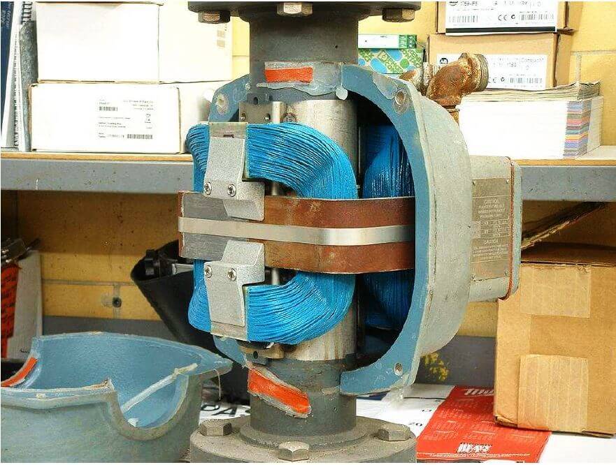
This photo of a Foxboro magnetic flow tube with one of the protective caps removed clearly shows these coils (blue):
Possibly the simplest form of coil excitation is when 60 Hz AC power obtained from line power supplies the coil, as is the case with this Foxboro flow tube.
Since the kinematic electromotive force is proportional to the fluid velocity and the flux density of the magnetic field, the induced voltage of such a coil will also be a 60 Hz sinusoidal wave whose amplitude changes with changes in volumetric flow rate.
Unfortunately, if there are any stray currents flowing through the liquid, creating a false voltage drop between the electrodes, then it's most likely 60 Hz AC as well.
With the coil powered at 60 Hz AC, any such noise voltage may be misinterpreted as fluid flow because the sensor electronics cannot distinguish between 60 Hz noise in the fluid and the 60 Hz motion EMF caused by the fluid flow.
A more sophisticated solution to this problem is to use pulsed excitation power for the flow tube coil.Electromagnetic flow meter manufacturerCalling this a DC stimulus is a bit misleading, as these "DC" stimulus signals are usually of opposite polarity and look more like an AC square wave on the oscilloscope display.
The moving emf of one of these flow meters will show the same waveform, the amplitude of which again becomes an indicator of the volumetric flow rate.
The sensor electronics can more easily reject any AC noise voltage because the frequency and waveform of the noise (60 Hz, sine wave) will not match the frequency and waveform of the flow-sensing motion EMF signal.
The biggest disadvantage of the pulsed DC electromagnetic flow meter is its slow response time to changes in flow rate.
To achieve the "best of both worlds", some electromagnetic flow meter manufacturers produce dual-frequency excitation flow meter that energize the flow meter coil at two mixed frequencies: one below 60 Hz and one above 60 Hz. The voltage signal intercepted by the electrode is demodulated and interpreted as flow rate.
Our experts are ready to helpWherever you are, DOWESTON's experienced engineering team is ready to support your product selection and applications - contact us today!
Tell us about your measurement task and we will help with product selection and technical questions.info@doweston.com
We value your privacy!
We and our partners use cookies and similar technologies to process personal data (such as IP address or browser information) in order to personalize the content and advertising shown to you. This helps us display more relevant content and improve your browsing experience. We also use it to measure results and tune website content. Because we value your privacy, we are asking for your permission to use these technologies. You can change or withdraw your consent at any time by clicking the settings button in the lower-left corner of the page.





 Home