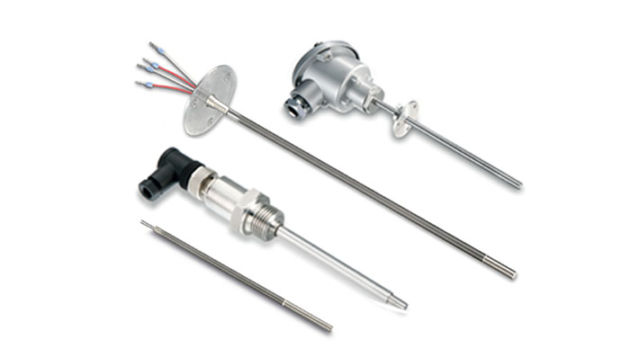
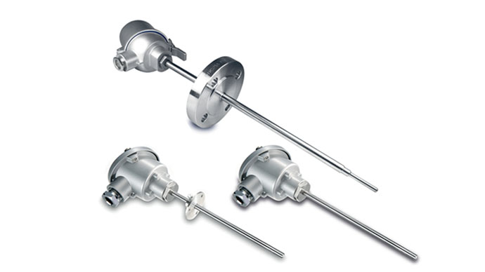
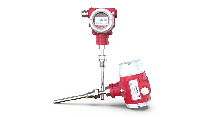
There are three basic types of RTDs: 2-wire, 3-wire, and 4-wire units, all of which are wired through bridge configuration circuits. An RTD is a metal component whose resistance changes with temperature. By connecting it into one leg of a Wheatstone bridge, its resistance can be measured. 2-wire RTDs are susceptible to errors caused by changes in lead resistance. To compensate for these and other errors, 3-wire RTDs and 4-wire RTDs are used when accuracy is required.
Input and output measurement standards
The application scope of the RTD determines the measurement standards used to check the instrument. A suitable input standard is a temperature bath. A standard thermometer must be placed in one of the wells to confirm the accuracy of the water bath. RTDs do not require temperature compensation. A voltmeter or decade resistance box can be used as an output measurement standard because they measure resistance. To check an RTD using a volt-ohm meter, a lookup table is required that relates the RTD resistance to temperature.
Number of connections
The two red RTD leads are connected to the positive meter lead and the black RTD lead is connected to the negative meter lead.
Three point check
Test the RTD under the following conditions: ambient temperature, mid-range temperature, and upper range temperature. RTD cannot be calibrated. If they are not within manufacturing specifications, the unit must be replaced.
When one end of a wire of two different thermoelectrically homogeneous materials is connected and placed in a temperature gradient, a thermoelectric voltage (EMF) is observed at the other end. This connection is called the measuring junction. On all thermocouples, the red lead is negative. The color of the other wire indicates the thermocouple type. For example, on a J-type thermocouple, the positive wire is white. Tables for each type of thermocouple list the voltages produced at different temperatures. Thermocouples should be inspected when there are signs that the output is incorrect. It may also be necessary to check the thermocouples that will be used to measure the standards.
Input and output measurement standards
A temperature bath can control the temperature for testing sensors. A hole in the temperature bath is used to hold the sensor during accuracy checks. The other hole is used to accommodate a measuring standard thermometer for confirming the actual bath temperature. A second measuring standard thermometer is used to read the ambient temperature at the reference junction. The sensor's output signal and range determine the measurement standard for the thermocouple output. Since the output is measured in millivolts, a millivolt meter is used to read the output.
Number of connections
Set up the temperature bath as the temperature input standard for the thermocouple. Choose an output standard with the appropriate range to read millivolts. Connect the red wire to the negative millivoltmeter input and the white wire to the positive millivoltmeter input.
Three point check
Since adjustments are not possible, we can only check the calibration of the thermocouple sensor. This check is typically performed at three test point input values: ambient temperature, mid-range temperature, and the upper limit of the application range. Recall that in a thermocouple, the temperature difference between the reference voltage and the measurement junction produces a millivolt voltage output.
Before inserting a thermocouple into the molten pool, determine the ambient temperature, which represents the temperature of the thermocouple's measurement junction. When using a lookup table that references 0 degrees, the ambient temperature must be compensated. The millivolt value of the ambient temperature in the table is added to the value of the sensor. This compensated millivolt value is used to determine the correct temperature from the table.
How to calibrate temperature transmitter?
The calibration of the temperature transmitter should be checked regularly.
The temperature transmitter discussed here receives an input signal from a thermocouple. Calibration requires a millivolt input signal, so a millivolt source can be used as the input standard. A milliammeter can be used to measure the output of the transmitter. Use a standard thermometer to calculate input signal compensation for ambient temperature. Finally, the transmitter needs to be powered.
To calibrate a temperature transmitter using a millivoltmeter as the input standard, any reference temperature other than 0 degrees must be compensated. C (32 degrees).
Number of connections
To make an input connection, the location of the reference junction must first be determined. When using thermocouple wire to connect a millivolt source to the transmitter, the reference junction is at the transmitter connection. Therefore, the ambient temperature in the transmitter housing is measured. If using copper wire, the reference junction is at the connection to the millivolt supply, so measure the ambient temperature at the millivolt supply. Always pay attention to the polarity of the leads. Connect the negative output of the millivolt power supply to the positive terminal of the transmitter. Place the milliammeter in series with the transmitter and power supply.
Set up device
Adjust the millivolt source and milliammeter to appropriate values as needed, turn on the device and begin calibration.
Five point check
Perform a five-point inspection to determine if the transmitter meets specifications.
Instrument accuracy
Start by adjusting the zero offset. The input value should be set to 10%. With zero set correctly, 10% input will produce 10% output. Use 90% input to adjust the span. Zeros and spans can be interacted with, inspected and readjusted as needed.
DOWESTON provides you with high-precision temperature sensors, including thermal resistors and thermocouples, and provides temperature calibration services.
Our experts are ready to helpWherever you are, DOWESTON's experienced engineering team is ready to support your product selection and applications - contact us today!
Tell us about your measurement task and we will help with product selection and technical questions.info@doweston.com
We value your privacy!
We and our partners use cookies and similar technologies to process personal data (such as IP address or browser information) in order to personalize the content and advertising shown to you. This helps us display more relevant content and improve your browsing experience. We also use it to measure results and tune website content. Because we value your privacy, we are asking for your permission to use these technologies. You can change or withdraw your consent at any time by clicking the settings button in the lower-left corner of the page.





 Home