Using a Coriolis Mass Flow Meter with a Pump
For applications that require very precise delivery of high-value liquid products, flow meters have long been the technology of choice.
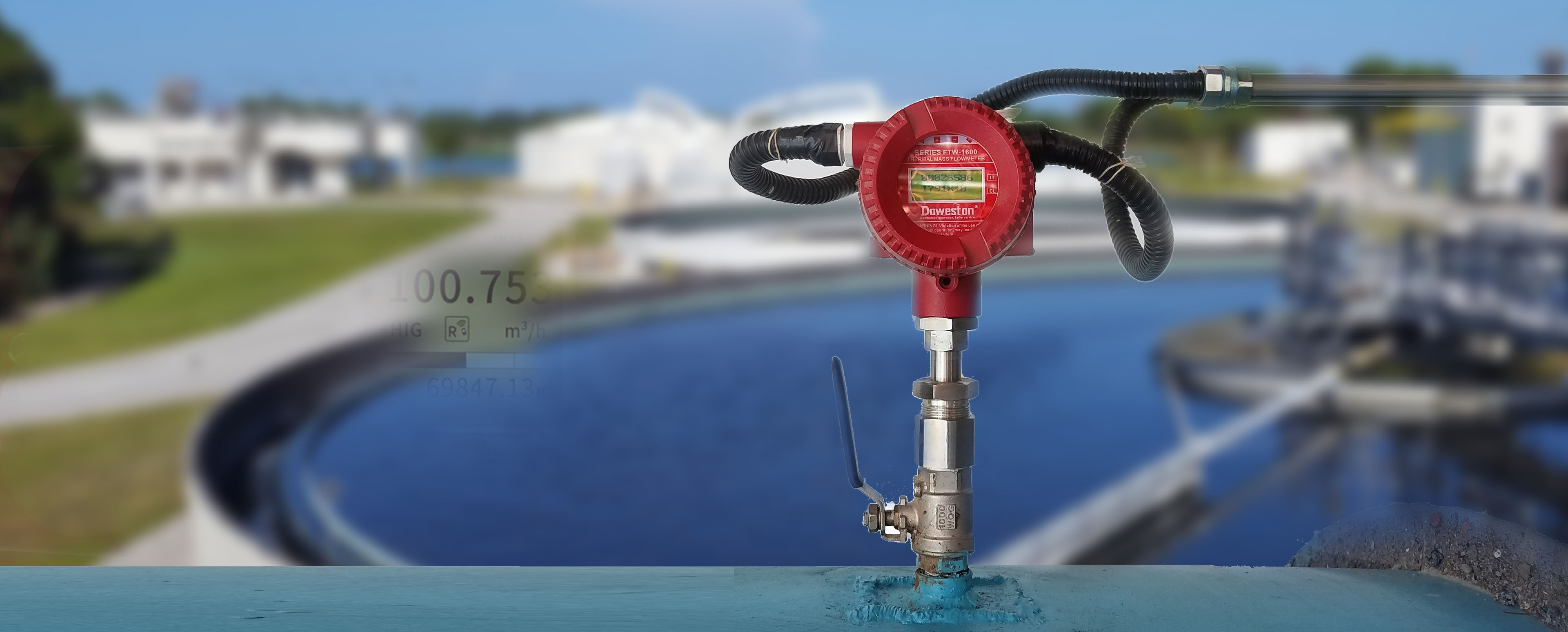
Recently,Mass Flow MeterAlready have a place in the market. These instruments have been successfully used in a variety of rotary power pumps and positive displacement pump systems. Rotary power pumps produce relatively smooth flow, while positive displacement pumps (such as piston, gear, and sliding vane pumps) produce pressure pulses during operation. Since mass flow meters use vibration to measure fluid flow, we question how well they would work with equipment that generates pressure pulses during operation. This study focuses on flow measurement in positive displacement pump systems that use a rotary sliding vane pump as the means of flow generation. Additionally, we narrowed our focus to relatively thin liquids. Transfers and changes in the custody of high value liquids (fuels) are the main focus of this study. We tested the meter on 30-SSU solvent and LPG (liquefied petroleum gas) to simulate one of the most common applications for our sliding vane pumps. Higher viscosity liquids were not considered and are outside the scope of this study. We tested the meter on 30-SSU solvent and LPG (liquefied petroleum gas) to simulate one of the most common applications for our sliding vane pumps. Higher viscosity liquids were not considered and are outside the scope of this study. We tested the meter on 30-SSU solvent and LPG (liquefied petroleum gas) to simulate one of the most common applications for our sliding vane pumps. Higher viscosity liquids were not considered and are outside the scope of this study.
Mass flow meter online selection engineer 
operating principle
Coriolis Mass Flow MeterFlow cannot be measured directly in terms of gallons per minute or cubic meters per hour (m3/hr). Instead, the fluid density and Coriolis force (mass flow rate) are measured, which are then used to calculate the flow rate.
Typically there are two measuring tubes in a Coriolis meter, which are formed into a slightly curved tube or a more dramatic "U" shape. The measuring tube through which the fluid flows is constantly expected to oscillate at its resonant frequency. The resonance frequency is the frequency at which the measuring tube "most likes" to vibrate. Any change in fluid density will produce a corresponding change in the resonant frequency of the entire vibrating system (measuring tube and fluid). Therefore, the resonant frequency is a function of the density of the fluid - the higher the density, the lower the resonant frequency. The resonant frequency is then compared to the empty pipe resonant frequency, allowing the fluid mass in the pipe to be calculated. Since the volume of the tube is known,
Typically, two tubes in a meter vibrate 180 degrees out of phase with each other. As flow (mass) passes through the meter, the phase angle between the tubes changes. The change in phase angle of the tube is caused by the Coriolis effect and is proportional to the mass flow rate of the fluid in the tube. Using the mass flow rate and dividing by the density gives the volumetric flow rate. Both density and mass flow rate are measured directly and are therefore independent of the temperature, pressure, viscosity, conductivity and flow curve of the fluid flowing through the meter. This means that in theory, a Coriolis mass flow meter can be used to measure any type of fluid flow. If desired, the meter's output can be corrected to a standard reference temperature.
There are several distinct advantages to using a Coriolis mass flow meter:
Because the fluid flows through a smooth tube with no moving parts, there is no mechanical wear on the measuring element. There are no parts that are abraded, corroded or corroded.
Particles almost as large as the diameter of the measuring tube can pass through the instrument without any problems. Typically, the diameter of the measuring tube is half that of the instrument piping connection for a two-pipe instrument and approximately equal to that of the piping connection for a single-pipe instrument.
Coriolis meters are not affected by temperature or pressure. They measure mass flow directly and do not change even if the temperature or pressure of the fluid changes. Therefore, no pressure or temperature compensation is required.
Accuracy is typically listed as 0.1% to 0.2% of the measured flow rate. This is much more accurate than mechanical meters, which are listed to within 0.5% of full-scale flow. Since other types of instrumentation also require pressure and temperature compensation, additional errors in these measurements can add up to 3% to the overall flow error.
Because of their very precise accuracy, Coriolis flow meters have a turndown ratio of approximately 100:1 or higher. This means that if the meter's maximum flow rate is 200 gallons per minute (757 liters), it is accurate to 2 gallons per minute (7.57 liters). A typical mechanical meter has a range ratio of 10:1. The turndown ratio of the orifice plate is closer to 5:1.
Coriolis mass flow meters with lower viscosity fluids have the smallest pressure drop. The only pressure loss is caused by splitting the flow into two measuring tubes. Orifice plate, flow nozzles, exhaust pipes, and positive displacement flow meters can cause significant pressure losses associated with flow meters.
Coriolis meters are not affected by viscosity changes during process or batch operation. Orifice plate and other differential pressure gauges need to be calibrated for various viscosities, and the viscosity needs to be measured during operation to ensure accurate metering.
Admittedly, there are some disadvantages to using a Coriolis mass flow meter that must be considered:
Compared to other technologies, such as ultrasonic or electromagnetic flow meters, the pressure drop across a Coriolis flow meter can increase significantly with increasing viscosity. The pressure drop is caused by splitting the flow into two or more smaller pipes that are not straight. Smaller elbows increase pressure drop compared to the straight-through flow of ultrasonic or electromagnetic flow meter.
Typically, the initial cost of a mass flow meter is higher than other technologies for similar applications.
Depending on the number of "bends" in the measuring tube, the space required to house a Coriolis flow meter can become quite large. However, this can be compensated by reducing the amount of straight pipe (flow correction) typically required on the inlet and outlet sides of many types of flow meter.
Flow Meter Experience To understand how a Coriolis mass flow meter interacts with a Blackmer® sliding vane pump, two flow meters were purchased. DOWESTON's first instrument was the 3-inch (76.2 mm) Model 83F. This meter is used to perform performance testing of various pumps on the 2000-30-SSU with 2000-SSU fluid. The second meter, an Emerson™ Micro Motion 2-inch (50.8 mm) model CMF200, was installed on Blackmer's propane test loop. The instrumentation was set up and installed, and pressure pulse and flow accuracy evaluated.
Setup and installation
DOWESTON meters are mounted on mobile carts. A 3-inch (76.2 mm) 100-mesh screen is installed on the inlet side. The pipe is looped around the cart with the elbow directly on the inlet side of the meter. This is done because, as recommended by both manufacturers, straight inlet pipe straightening is not required on the inlet or outlet side of the meter. The manufacturer recommends mounting the meter vertically to allow easier air removal when the meter is empty. However, the meter was intentionally mounted horizontally to investigate the effects of incorrect meter mounting orientation. Typical use of this meter is to test a pump with a specified fluid and viscosity, drain the pump and piping system, and then install it with another pump with the specified fluid.
Emerson instruments are also installed horizontally in the LPG test loop. However, to comply with LPG custody transfer regulations, a water eliminator and check valve are installed on the meter. This system is also used in a similar manner: the pump is tested, the pipes are drained, and the pump is removed for the next pump installation. The Emerson meter has a flow rate of nearly 400 gpm of water.
The following observations and lessons can be learned from using electricity meters:
Both instruments have pressure pulse attenuation software. This feature is disabled on both meters. Testing showed it was not necessary.
Flow readings from both meters were surprisingly smooth and much lower than any PD meter used before. For a flow rate of 40 gallons (151.42 liters) per minute, Emerson meters fluctuate on LPG at ±0.1 gallons per minute. DOWESTON meters have similar fluctuations, which may be as high as ±0.3 gallons per minute (1.14 liters) or even greater at flow rates up to 300 gallons per minute (1136 liters).
Coriolis mass flow meters are acoustically much quieter than PD flow meters. This is especially noticeable on gauges on LPG systems. Since there are no moving parts, there are no vibrations that would resonate with the associated pipes. However, when the meter is powered and not filled with fluid, the meter will make a high-pitched buzzing sound. The buzzing sound can be eliminated by filling the meter with liquid or by removing power from the meter.
An LPG flow meter with a vapor elimination system has no difficulty reading the flow rate when empty. Because the back pressure valve and vapor elimination valve eliminate vapor so well, the meter fills with liquid just as quickly as the previously used PD meter.
It is difficult to remove air from the DOWESTON meter, which is intentionally mounted horizontally on a mobile cart. Both manufacturers recommend mounting the meter vertically, and this advice has proven to be correct. With a flow rate of over 100 gallons per minute (378.54 liters), it successfully clears air in a very short time (less than a minute). At lower flow rates (less than about 75 gallons [284 liters] per minute), use a valve to throttle the meter's outlet to increase the pressure in the meter. This allows the trapped air to dissolve in the test fluid and flush out of the meter after a few minutes. Below about 30 gallons (113.56 liters) per minute, complete removal of air is impossible.
Air in the meter can create turbulence and reduce the accuracy of density measurements. Air in the meter can also cause density measurements to become unstable, which can be observed on the meter recorder. During normal operation, density fluctuations are typically ±.0005 SG or less – all the way to the fourth decimal place or tenths. When there is air in the system, the change in SG is approximately ±.05, which is two orders of magnitude greater than when there is no air.
Orient the meter vertically to test the degassing process. After about five minutes of operation, if the flow rate is less than 3 gallons per minute (800 gallons per minute [3028 liters] per minute meter), the air can be flushed from the meter without using a throttle. The outlet side of the instrument. As the flow rate increases, or by throttling the outlet of the flow meter, air removal can be completed in a shorter time.
Pressure pulse
One point of concern when using a Coriolis mass flow meter with a positive displacement pump is that the PD pump produces pressure and flow pulses that the Coriolis flow meter may respond to. PD pumps move fluid by filling a fixed volume chamber and then forcing the fluid out of the chamber. PD pumps may have only one chamber, such as a single piston pump, or they may have twenty or more, such as a gear pump. Pressure pulses are created by filling and emptying each individual pumping chamber, and the frequency of the pulses is a function of the number of chambers in the pump and the operating speed of the pump. Coriolis mass flow meters measure the vibration of the pipe and the change in frequency of the pipe to measure flow.
Theoretically, distortion in flow meter vibration measurements will tend to maximize near the frequency at which the flow meter operates. Through discussions with the mass flow meter manufacturer, the resonant vibration of the mass flow meter is approximately 200 Hz. To evaluate the possible interference of pressure pulses in flow measurements, several sliding vane pumps were tested at nominal 100 psi and the shaft speed was varied to create vane frequencies ranging from 80 Hz to 260 Hz. Collect high-speed pressure and flow data and record minimum and maximum pressure and flow. The results show that there is no correlation between the blade frequency, pressure pulsation and the measured flow rate of the flow meter.
Another attempt was made to look for possible interference between the pump and flow meter. For comparison, the pump was operated at sliding vane frequencies of 120 Hz and 200 Hz (Figures 2 and 3), with the pressure in the pump outlet and flow meter maintained at a nominal 100 psig. Monitor flow and pressure signals from flow meters and pressure sensors with a digital signal processing oscilloscope.
The Coriolis flow meter used for testing provided a frequency output signal that produced a 50% on/off square wave function between 0.5 VDC and 22.5 VDC. The number of on/off cycles produced by the meter per unit time is directly proportional to the flow through the meter. When operating under the above conditions, check the flow meter's signal for voltage value distortion, the shape of the output function, and the timing of each signal step over time. No significant distortion of the output wave was found except for minor pressure and flow fluctuations within the expected values of the system. Figures 2 and 3 show sample results.
The final study performed was to operate a sliding vane pump using the same vane passage frequency as the resonant frequency of a Coriolis mass flow meter and record the output waveform from this flow meter and then compare it to the same conditions and to a pulse-free flow from the flow meter. Rotating flow source. The vane pump operates at a sliding vane pass frequency of 200 Hz to maximize the chance of instrument resonance. The flow rate and operating conditions of both pumps were maintained at 19.5 gallons per minute (73.82 liters) and 100 psig pressure on the 30-SSU solvent. The results (Figure 4) show that the waveforms are identical. The meter handles both types of flow (pulsed and non-pulsed) with the same accuracy.
Looking to the future
We will examine test results at different flow rates as well as field observations. The analysis will show that the goals of significantly improved measurement accuracy and very good reliability in a production environment can be achieved and documented.
For more information on mass flow meter applications, please view our application cases





 Home


