5 factors that affect thermal mass flow meter accuracy, flow curve and adjustment, learn to become a master in seconds
The end user's knowledge of the application conditions is critical to making a flow meter easy to use. But many times we have to provide different types of customers with the application knowledge of flow meters and solve various application problems.
First the velocity curve is used to determine the flow rate of the fluid flowing within the pipe. If the fully deployed profile changes, the accuracy of the thermal mass flow meter will decrease. In addition, five application factors that affect instrument accuracy need to be considered. One of these includes straight-line travel distance upstream, which changes the flow profile. Flow conditioning, a comprehensive process of creating a more uniform flow profile, is necessary in many cases when the length of the upstream straight pipe section does not allow for a sufficiently developed flow profile.
This article reviews the fundamentals of flow profiling, five end-user application considerations, and explores how flow conditioning can be used to improve flow meter accuracy in areas where adequate flow curves are not available.
Fluids such as gases flow through pipes at different speeds. When gas enters a circular pipe, particles in contact with the pipe surface stop, forming a boundary layer. Gas flowing in adjacent layers is slowed down due to friction, and the gas velocity increases in the middle section to maintain the mass flow rate through the pipe. The velocity distribution on the pipe is the velocity curve. Once the flow is "fully unfolded," the flow curve becomes parabolic. By knowing the velocity distribution, the velocity at any location in the pattern can be determined.
By knowing the velocity distribution, the velocity at any location in the pattern can be determined.
By knowing the velocity distribution, the velocity at any location in the pattern can be determined.
Whenever the flow profile decreases, the accuracy of the meter decreases. The main factors affecting the flow distribution are the pipes and straight pipes upstream of the flow sensor, while the downstream straight pipes have less influence. Ideally, the required fully developed flow curve is achieved by a smooth, long-running straight pipe before the instrument sensor. However, in the real world, most pipes do not have enough straight pipe and are damaged due to fittings/joints, expanders, pressure reducers, valves, tees, headers, elbows, strainers, strainers, knockout tanks, heat exchangers, regulators, valves, flanges and elbows.
DOWESTON provides you with various types of high-precision flow meter, including electromagnetic flow meter, Vortex flow meter, turbine flow meter, etc.
Typically, a straight line run in front of the flow meter requires increased distance to deliver a proper flow curve. For example, when introducing an elbow in the same plane of the pipeline, the diameter of the upstream straight pipe will be required to be 25. Other upstream configurations require even longer lengths. Often, it is not possible to obtain sufficient straight line travel to ensure a fully developed flow profile. In these cases, flow conditioning is an excellent option to explore.
Effect of 90-degree elbow on velocity distribution
Effect of 90-degree elbow on velocity distribution
"Location, location, location"
The location of the flow meter is essential and often overlooked. Choosing an installation location based solely on ease of installation is often short-sighted. End users should consider flow disturbances at that location before selecting a meter location. Therefore, give careful consideration to determining the most effective site. Regardless, once a location is selected, the interference should be determined so that the manufacturer can determine if flow adjustment is required, and if so, the flow meter will have been adjusted at the factory.
flow meter factory calibration
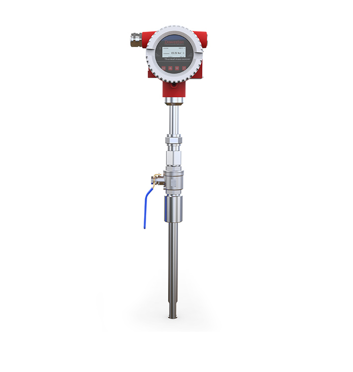
The flow meter sensor probe must be installed in the center of the pipe.
When measuring gases using a thermal mass flow meter, it is important that the manufacturer understands the process conditions under which the end user will use the meter. This allows the manufacturer to calibrate the instrument to the environment of the application. Otherwise, inaccurate flow rates may result.
During manufacturer's bench calibration, a controlled amount of a specified gas flows through the sensor and the signal is measured. This process is repeated multiple times over the operating range to determine the relationship between mass flow rate and calibration gas and sensor signals.
Pipe Sizing-In addition to identification, piping plans, and full-scale flow rates (or maximum velocities) of gas flow, pipe sizing should be checked at the installation site. Communicate this information to the manufacturer for proper calibration.
Gas Composition - The meter must be calibrated with the gas that the end user is measuring since each gas has different thermal properties. Additionally, any change in gas composition will produce erroneous results. While some gases may be nearly pure (such as nitrogen or argon), others (such as biogas) are composed of mixtures of gases with varying component contents. In the latter case, changes in components including methane and CO content must be understood. Communicate this information to the manufacturer for proper calibration.
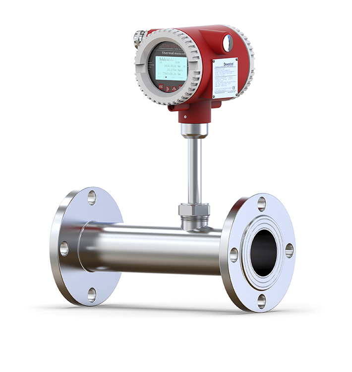
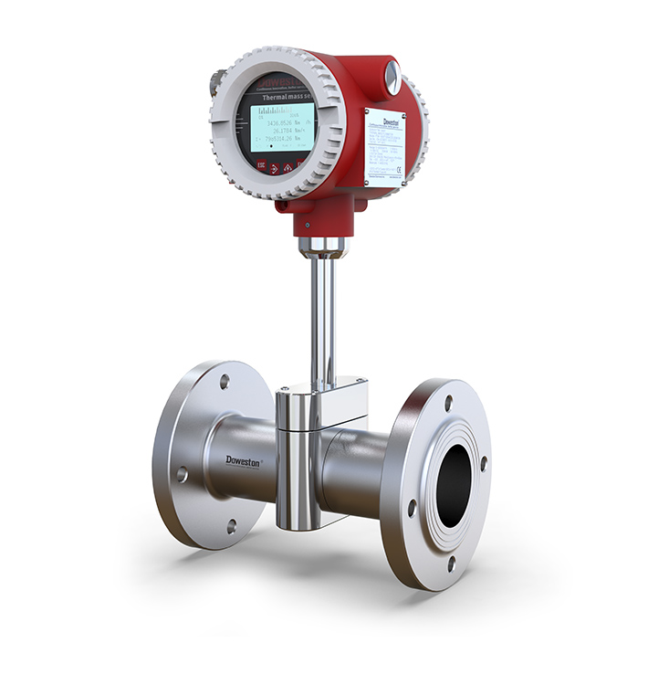
Inline body flow regulation
Moisture-If moisture or particles are present in the gas, modifications to the installation may prevent condensation from hitting the sensor. The main principle of thermal mass flow measurement involves heat transfer caused by air flow. Condensed moisture in the gas in contact with the heated sensor rapidly increases heat transfer and the instrument produces a spiked response, resulting in inaccurate flow measurements. The following can resolve moisture issues when measuring with thermal mass flow meters: A) Position the sensor at a 45 degree angle to the pipe so that if condensation forms in the pipe wall, gravity will force the moisture away from the sensor. B) When using a separation tank or separation tank, moisture and gas drip separately. In this case, the gas flows into the container, where a decrease in velocity and a change in direction occur. Gravity causes the water to fall while the gas flows upward and out, removing the water from the gas. C) In some cases, thermal tape can be applied to the outside surface of the pipe to prevent condensation.
Straight upstream-the location of the meter is critical. Disturbances can negatively affect the direction of airflow. The greater the flow disturbance upstream, the longer the length of straight pipe upstream will take to achieve the required fully developed flow profile.
Insertion Depth-The flow meter sensor probe must be located in the center of the pipe because the highest flow rates will be detected furthest from the pipe wall. There are at least two methods for inserting a probe into the center of a pipe. 1
Captive Flow Regulator for Insertion Flow Meter
Flow regulation pass-through requirements
Multiple disturbances upstream of the flow meter can have a cumulative effect on the flow curve. If the correct straight pipe upstream length cannot be achieved at the flow meter, flow adjustment can be performed.
Flow regulators (also called rectifiers) provide even flow distribution at the sensor location. This consistent flow curve is different from the fully developed flow curve that occurs at acceptable straight pipe lengths, so the flow meter characteristics must be calibrated using a flow regulator with knowledge of other site parameters (e.g., gas type, piping, upstream straight pipe run length (and interference), and installation depth).
Flow Regulator-If straight flow is insufficient, two flow regulator styles provide an even flow curve.
Online flow meter - For an online flow meter, the flow meter has a flow regulating device built into it.
Captured Flow Regulator-For insertion-type meters, a captured flow regulator assembly consisting of two regulating plates located between two flanges is available. The end user provides the flange for this configuration.
Table 1. This figure illustrates the importance of using the recommended upstream pipe diameter for flow regulation.
Table 1. This figure illustrates the importance of using the recommended upstream pipe diameter for flow regulation.
Table 1 shows the required upstream straight pipe length for various piping configurations with and without flow conditioning before the flow meter location. This applies to straight tube and insertion flow meter (built-in flow meter).
In all cases, flow regulation can significantly reduce the recommended upstream distance in front of the meter.
The result we get is
Consider in any applicationthermal mass flow meterAlways be smart about your location and understand that the most convenient location may not yield the most accurate results. Provide the thermal mass flow meter manufacturer with the end user's usage conditions (piping information, gas or gas mixture, process pressure, and upstream straight pipe sections and interferences) so that it can be determined whether flow regulation is required. The meter can then be properly factory calibrated to produce the meter best suited for the application.
Our experts are ready to helpWherever you are, DOWESTON's experienced engineering team is ready to support your product selection and applications - contact us today!
Tell us about your measurement task and we will help with product selection and technical questions.info@doweston.com
We value your privacy!
We and our partners use cookies and similar technologies to process personal data (such as IP address or browser information) in order to personalize the content and advertising shown to you. This helps us display more relevant content and improve your browsing experience. We also use it to measure results and tune website content. Because we value your privacy, we are asking for your permission to use these technologies. You can change or withdraw your consent at any time by clicking the settings button in the lower-left corner of the page.





 Home