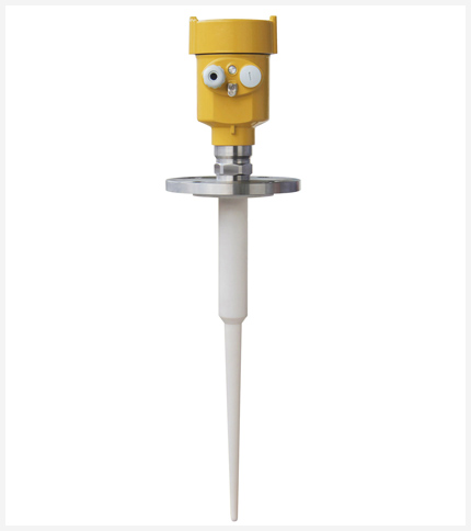
Applicable medium: liquid, slightly corrosive liquid
Application: sewage liquid level measurement; low volatile acid and alkali liquid level measurement; slurry level measurement
explosion-proof certification: Exia IIC T6 Ga/ Exd IIC T6 Gb
Measuring range: 20m
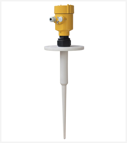
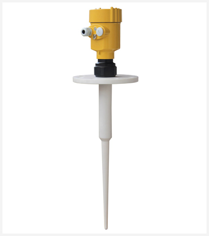
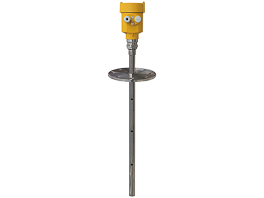
antenna: rod antenna (PP/PTFE)
Frequency: 6 GHz
process temperature: (-40~130)°C
The 6GHz intelligent series radar level meter is suitable for non-contact continuous measurement of the level of liquids, slurries, granules and blocks. It is suitable for situations where temperature and pressure change greatly, and where inert gases and volatilization are present.
It adopts microwave pulse measurement method and can work normally within the industrial frequency band. The beam energy is low and can be installed in various metal and non-metal containers or pipes without harming the human body or the environment.
Very short microwave pulses of very low energy are transmitted and received via an antenna system. Radar waves travel at the speed of light. The operating time can be converted into a level signal via electronics. A special time-stretch method ensures stable and precise measurements over extremely short periods of time. Even if the working conditions are relatively complex and there are false echoes, microprocessing technology and debugging software can be used to accurately analyze the echo of the material level.
The antenna receives the reflected microwave pulse and transmits it to the electronic circuit. The microprocessor processes the signal and identifies the echo generated by the micro-pulse on the surface of the material. Correct echo signal identification is completed by pulse software, and the accuracy can reach millimeter level.
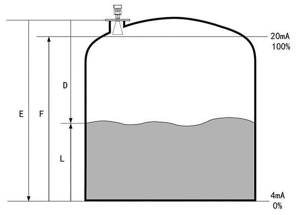
The distance D from the material surface is proportional to the time travel T of the pulse: D=CxT/2; where C is the speed of light. Since the distance E of the empty tank is known, the material level L is: L=E-D.
Set by inputting the empty tank height E (= zero point), the full tank height F (= full scale) and some application parameters. The application parameters will automatically adapt the instrument to the measurement environment. Corresponds to 4-20mA output.

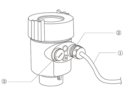
This instrument fully meets the requirements of protection grade IP66/67. Please ensure that the cable sealing head is waterproof. As shown in the picture
How to ensure your installation meets IP67 requirements:
Make sure the sealing head is not damaged.
Make sure the cable is not damaged.
Make sure that the cables used comply with the electrical connection specifications.
Before entering the electrical interface, bend the cable downwards to ensure that water does not flow into the housing, see ①
Please tighten the cable sealing head, see ②
Please seal the unused electrical interfaces with blind plugs, see ③
inquiry hotline: +1 (314) 325-4420

Applicable medium: liquid, slightly corrosive liquid
Application: sewage liquid level measurement; low volatile acid and alkali liquid level measurement; slurry level measurement
explosion-proof certification: Exia IIC T6 Ga/ Exd IIC T6 Gb
Measuring range: 20m
antenna: rod antenna (PP/PTFE)
Frequency: 6 GHz
process temperature: (-40~130)°C
measurement Accuracy: ±10mm
process pressure: (-0.1~0.3)MPa
signal output: (4~20)mA/HART
On-site display: four-digit LCD programmable
Power supply: 2-wire (DC24V) 4-wire (DC24V/AC220V)
Repeatability: ± 1mm
Housing: Aluminum single cavity/aluminum double cavity/plastic/stainless steel single cavity
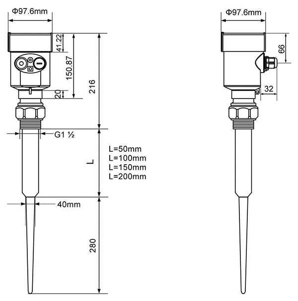
Process connection: flange (optional)/thread

LRD-180
| General data | Material | Antenna | PTFE, PP |
| Enclosure | Aluminum, plastic, anti-static PP, stainless steel 316 | ||
| Seal between housing and housing | Silicone rubber | ||
| Housing window | Polycarbonate | ||
| Ground terminal | Stainless Steel | ||
| Process connection | 1 | G1½″A thread or 1½″NPT thread/flange | |
| LRD-1802 | PTFE flange flange | ||
| LRD-1803 | Stainless steel flange | ||
| LRD-1804 | Stainless steel flange | ||
| LRD-1805 | Stainless steel flange | ||
| LRD-1806 | Stainless steel flange | ||
| Supply voltage | Two-wire | Standard version | (16~26)V DC |
| Intrinsically safe version | (21.6~26.4)V DC | ||
| Power Consumption | max. 22.5mA | ||
| Permissible ripple | |||
| -<100Hz | Uss < lV | ||
| - (100~100K)Hz | Uss < l0mV | ||
| Flameproof version | (22. 8~26. 4) V DC 2-wire | ||
| (198~242) V AC 4-wire / 110V AC 4-wire | |||
| Power Consumption | max. 1VA, 1W | ||
| Cable specifications | Cable entry / connector | 1 M20xl.5 cable entry (cable diameter 5~9mm) | |
| 1 blind plug M20xl.5 | |||
| Spring terminal block | For conductor cross-section 2.5mm² | ||
| Output specifications | Output Signal | (4~20)mA/HART | |
| Resolution | 1.6μA | ||
| Fault signal | Current output remains unchanged; 20.5mA; 22mA; 3.9mA | ||
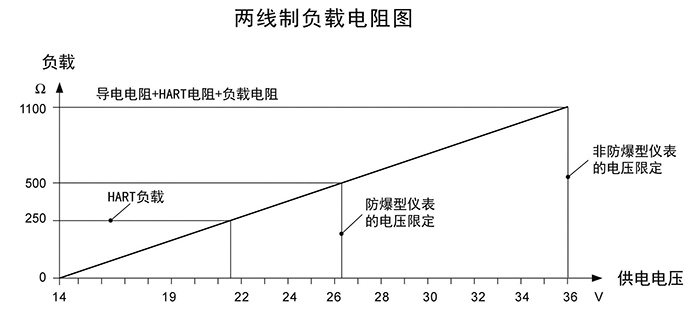
| 2-wire load resistance | See picture below | ||
| 4-wire load resistance | Maximum 500Ω | ||
| Integration time | (0-36) s, adjustable | ||
| Characteristic parameters | Blind zone | Antenna tip | |
| LRD-1801 | 20m ( liquid ) | ||
| LRD-1802 | 20m ( liquid ) | ||
| LRD-1803 | 35m | ||
| LRD-1804 | 35m | ||
| LRD-1805 | 20m | ||
| LRD-1806 | 15m | ||
| Measurement interval | About 1s (depends on parameter settings) | ||
| Adjustment time | About 1s (depends on parameter settings) | ||
| Resolution | 1mm | ||
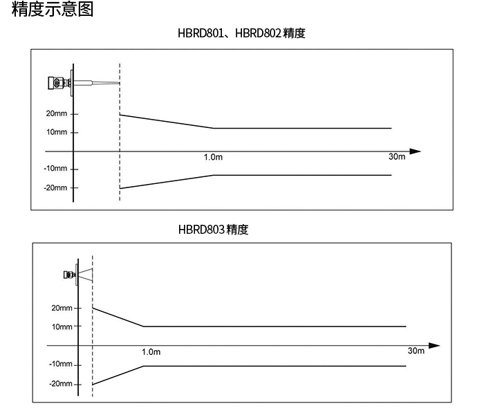
| Accuracy | 10mm or <0.1% (see accuracy diagram below) | ||
| Operating, storage and transport temperature | (-40 to 80)°C | ||
| Process temperature (at the antenna) | |||
| LRD-1801 | -40 to 130°C | ||
| LRD-1802 | -40~130°C ( standard type ) / -40~180°C ( high-temperature type ) | ||
| LRD-1803 | -40~130°C ( standard type ) / -40~180°C ( high-temperature type ) | ||
| LRD-1804 | -40~130°C ( standard type ) / -40~180°C ( high-temperature type ) | ||
| LRD-1805 | -40~130°C ( standard type ) / -40~180°C ( high-temperature type ) | ||
| LRD-1806 | (-40 to 400)°C | ||
| Relative Humidity | <95% | ||
| Tank pressure | Max. 4MPa | ||
| Vibration resistant | Mechanical vibration 10 m/s², (10-150) Hz | ||


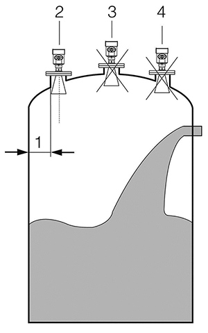
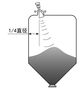
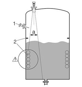
Recommended position (2), the tank wall to the outer wall of the short pipe installation should meet the following requirements: the optimal distance from the tank wall is 1/4 or 1/6 of the tank diameter, and the minimum installation distance from the tank wall is 1/10 of the measurement range. For example: for a 10m liquid level storage tank, the minimum installation distance from the tank wall should be 1m.

●Cannot be installed above the material inlet (4)
● It cannot be installed in the center (3). If installed in the center, multiple false echoes will be generated, and interference echoes will cause the loss of the real signal.
● If the distance between the instrument and the tank wall cannot be maintained, the medium on the tank wall will adhere and cause false echoes. False echoes should be stored when debugging the instrument.

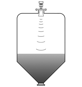
Installation of conical tanks
The flat top of the conical tank can be installed in the middle of the tank top to ensure that the conical bottom is measured.

Stacked storage tanks
When there is a material pile, the antenna should be aligned vertically with the material surface. If the material surface is uneven and the stacking angle is large, a universal flange must be used to adjust the horn angle so that the horn is aligned with the material surface as much as possible. (Because the inclined solid surface will cause echo attenuation and even signal loss)

Tank installation instructions
Within the signal beam, the following installation objects should be avoided: such as (1): limit switch, temperature sensor, etc.
Symmetric devices such as (2): vacuum ring, heating coil, baffle, etc.
If there are (1) (2) interfering objects in the tank, a waveguide should be used for measurement.

Tell us about your measurement task and we will help with product selection and technical questions.info@doweston.com